Get Started
Sensors Guide
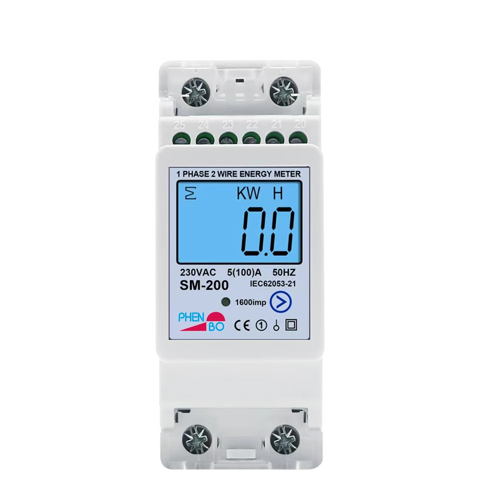
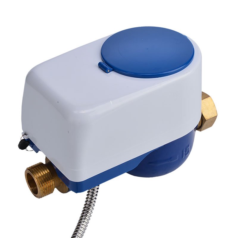
A wide range of Modbus sensors work with Radius devices out of the box.
- We support protocols, not individual sensors — our devices are compatible with a very wide range of sensors that support every possible application
- Browse our sensor catalog, and use the Billing Supported filter to see which sensors support billing
Don't see your sensor?
We're always expanding supported sensor models. Let us know what you're using and we'll help you get it integrated — please send the sensor's datasheet along with its model and vendor name.
Request Sensor SupportConnecting Sensors
Wire up to 7 Modbus sensors to a single Radius device on one RS-485 bus.
Wire the RS-485 bus
Connect the sensor's A/B (D+/D-) terminals to the Radius device's Modbus terminal, along with a shared GND.
Set a unique Modbus address
Each sensor on the bus needs its own slave address (1–247) so the device can tell them apart.
Power the sensor
Confirm the supply voltage matches the sensor's spec sheet before connecting power.
The I²C wiring guide is coming soon.
Mobile App
Monitor and manage your Radius devices from anywhere, on iOS or Android.
1. Download the app
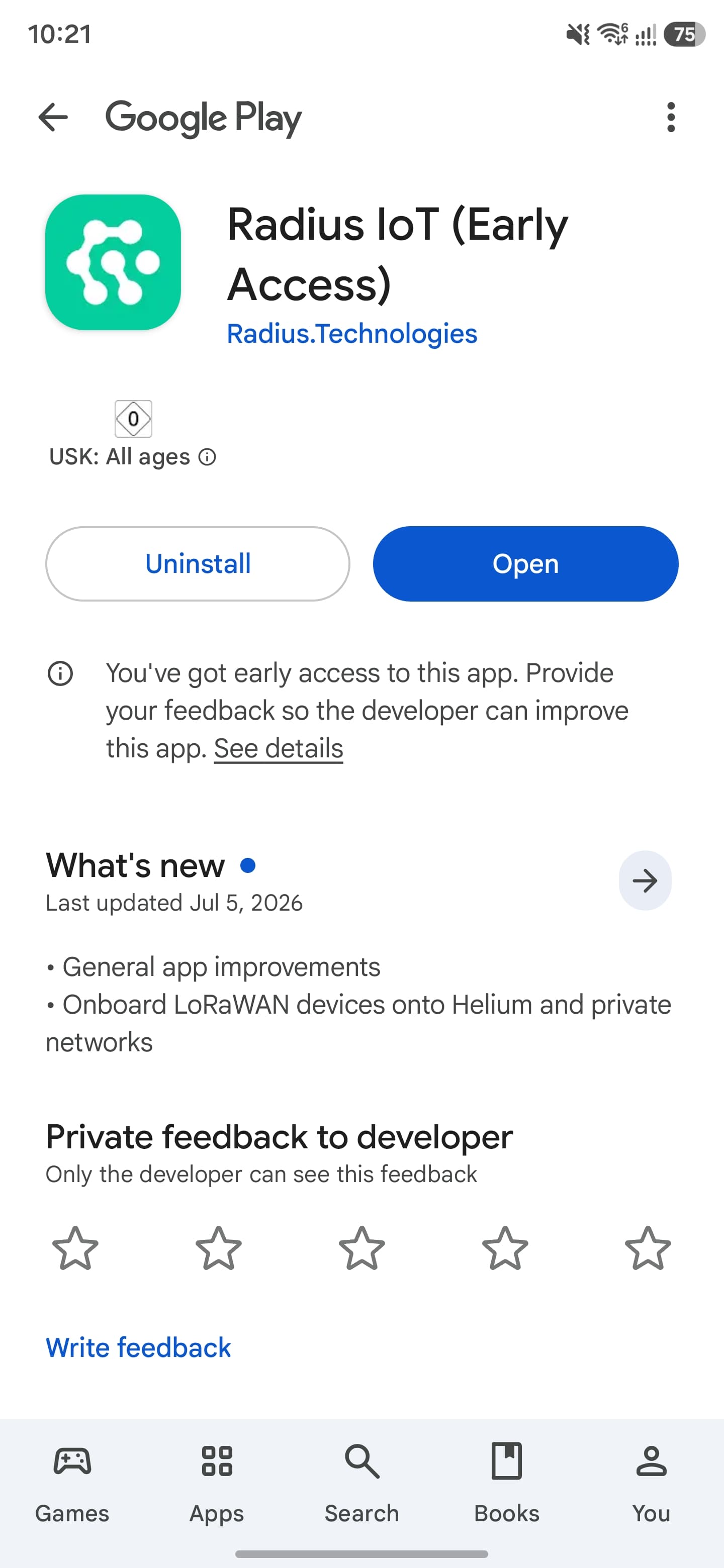
Available on the App Store and Google Play.
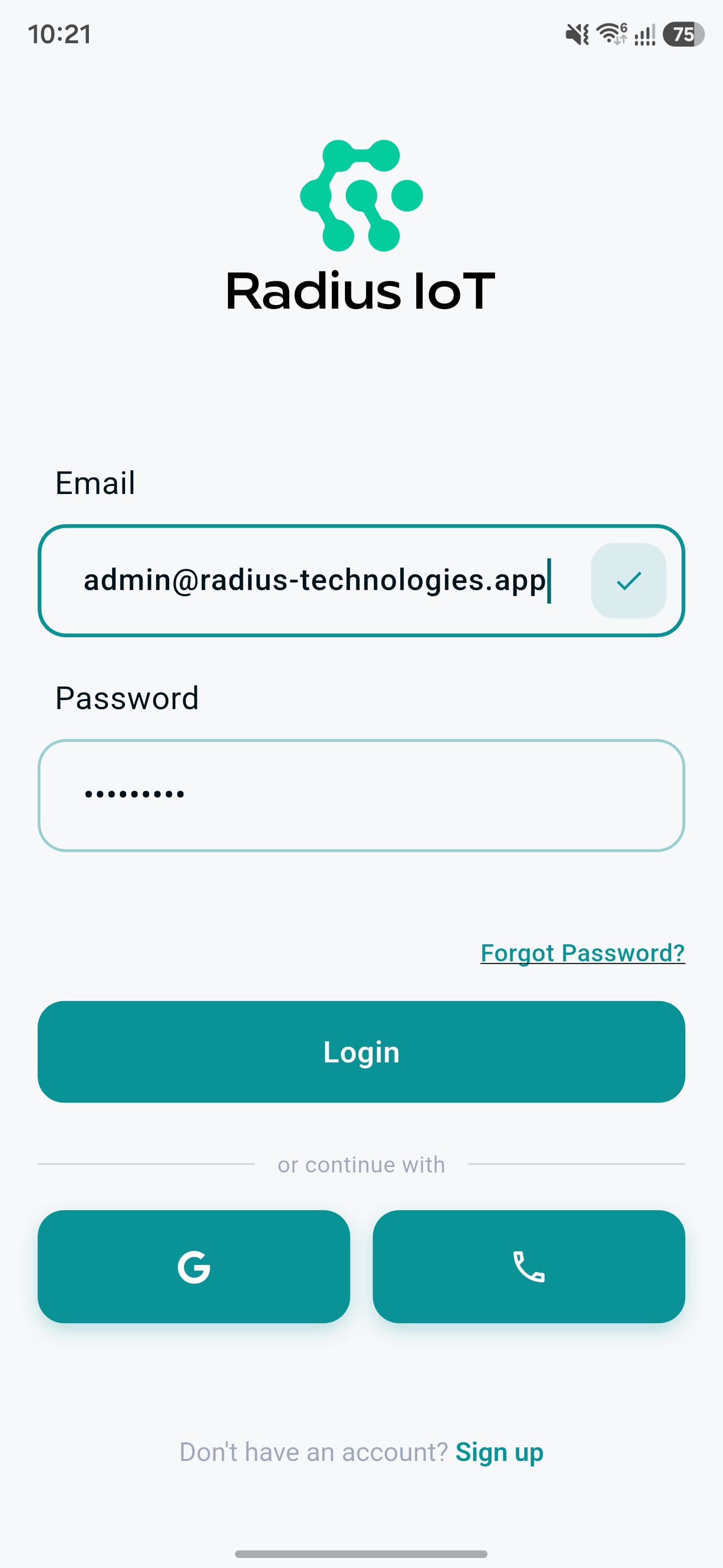
2. Sign in
Use your Radius account credentials, Google, or phone number.
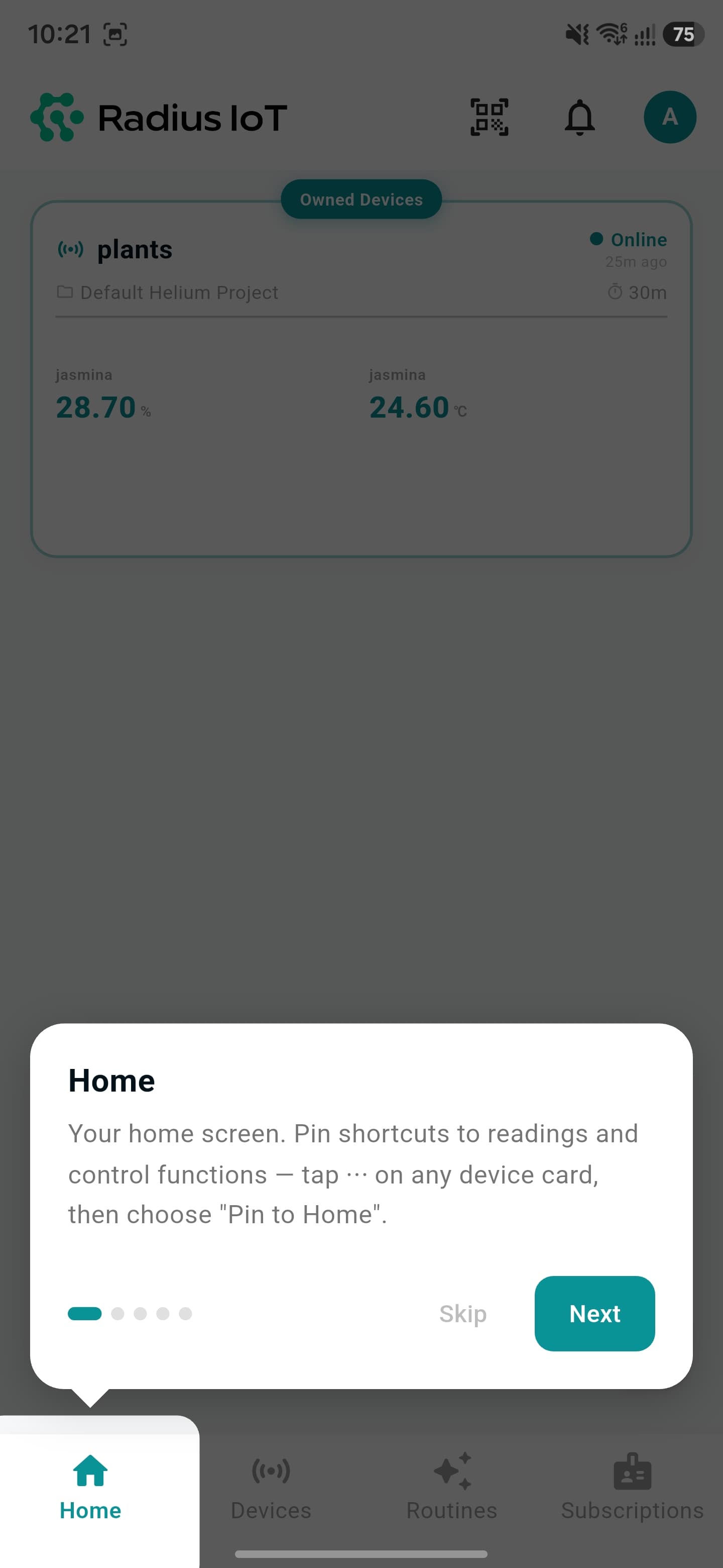
3. Take the home tour
A quick onboarding walkthrough shows you around.
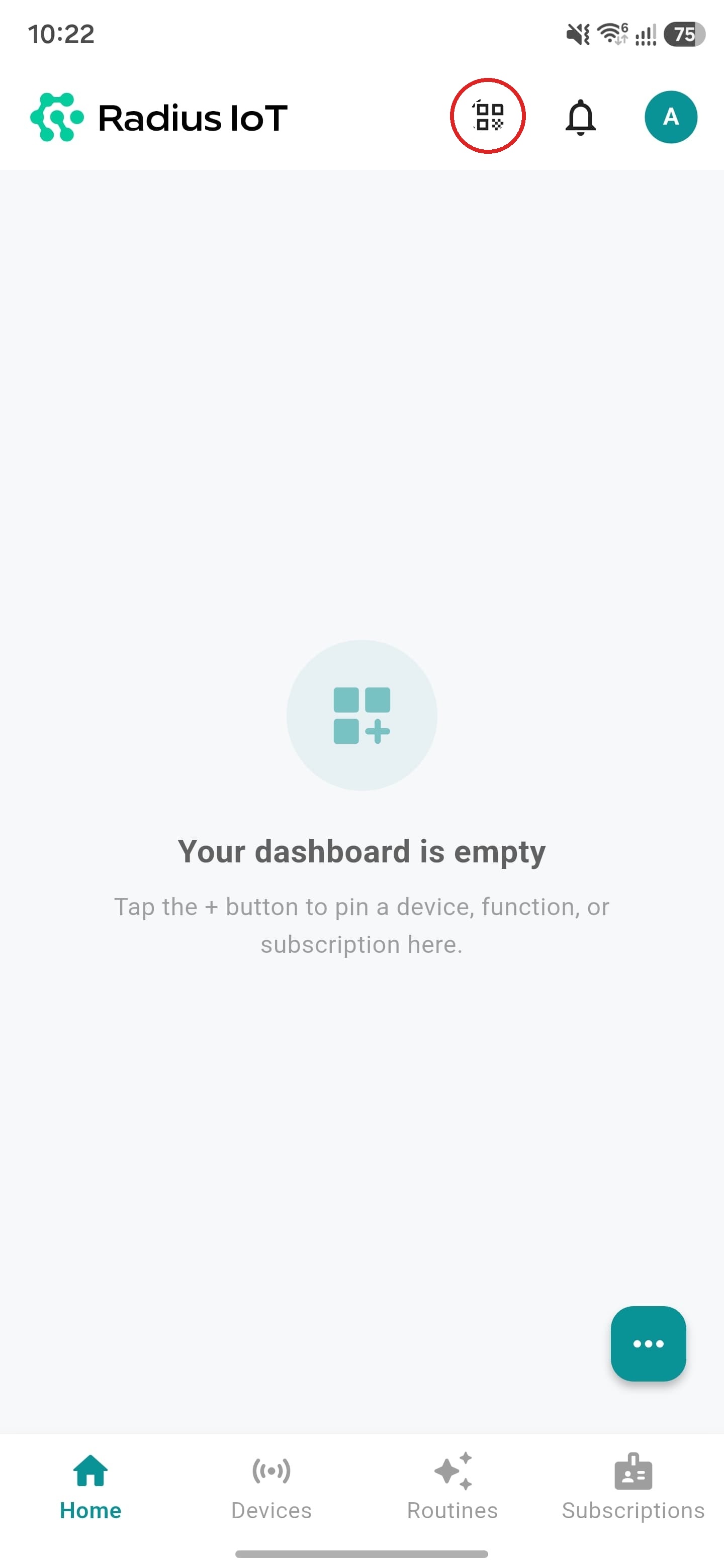
1. Tap the scan button
From your home screen, tap the scan icon to start adding a device.
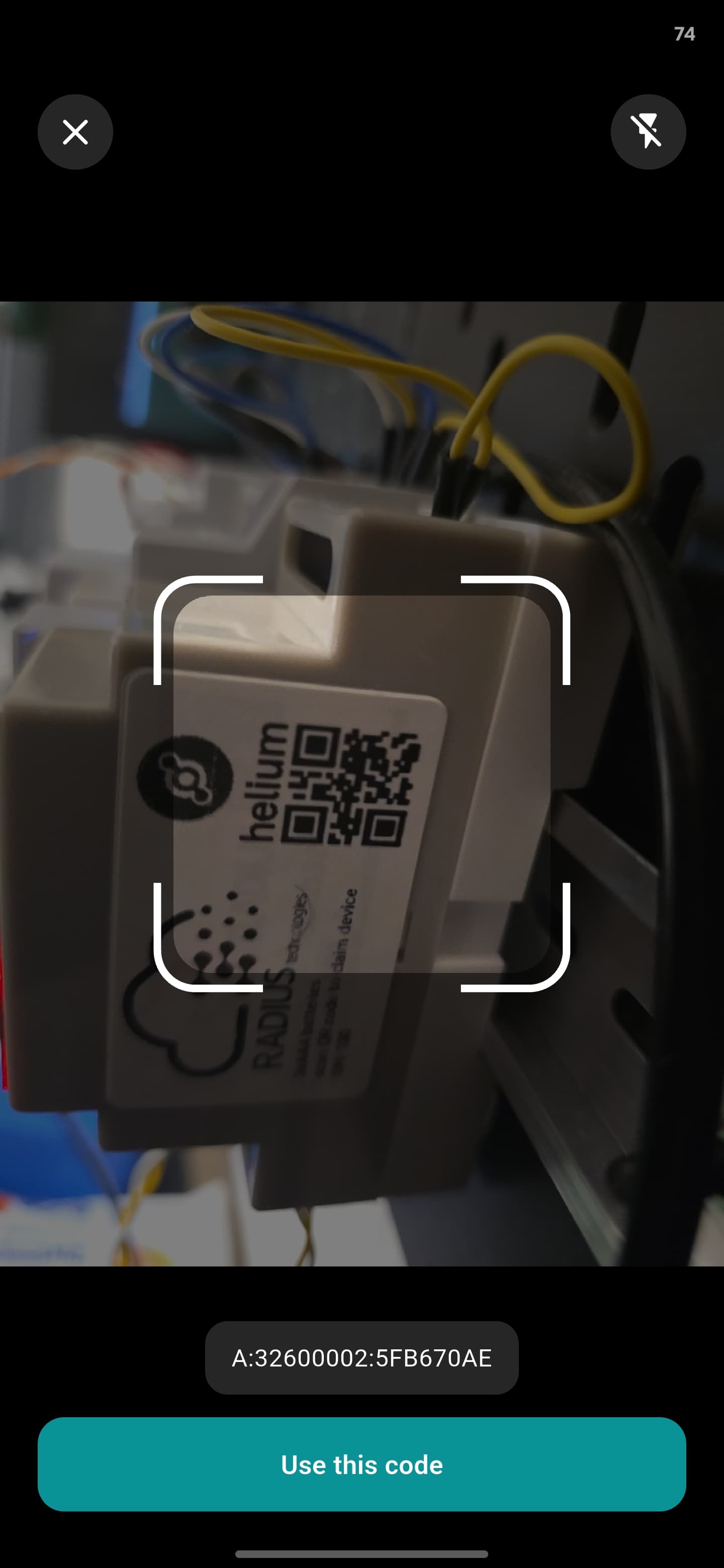
2. Scan the QR code
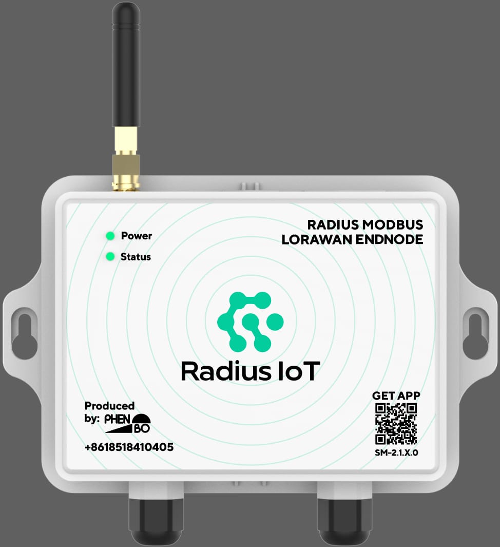
Point the camera at the QR code printed on the device label.
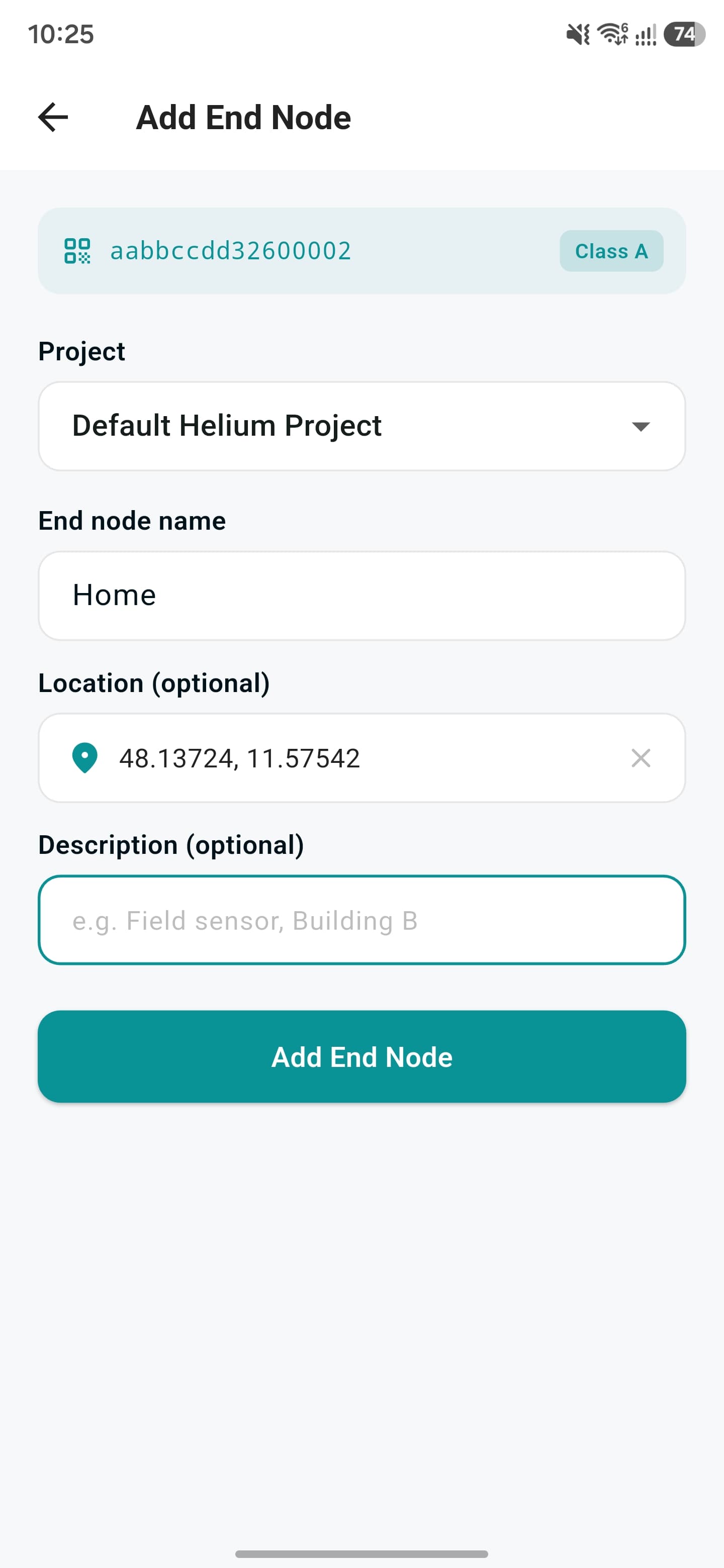
3. Fill in the details
Choose the project, name the device, and tap "Add End Node".
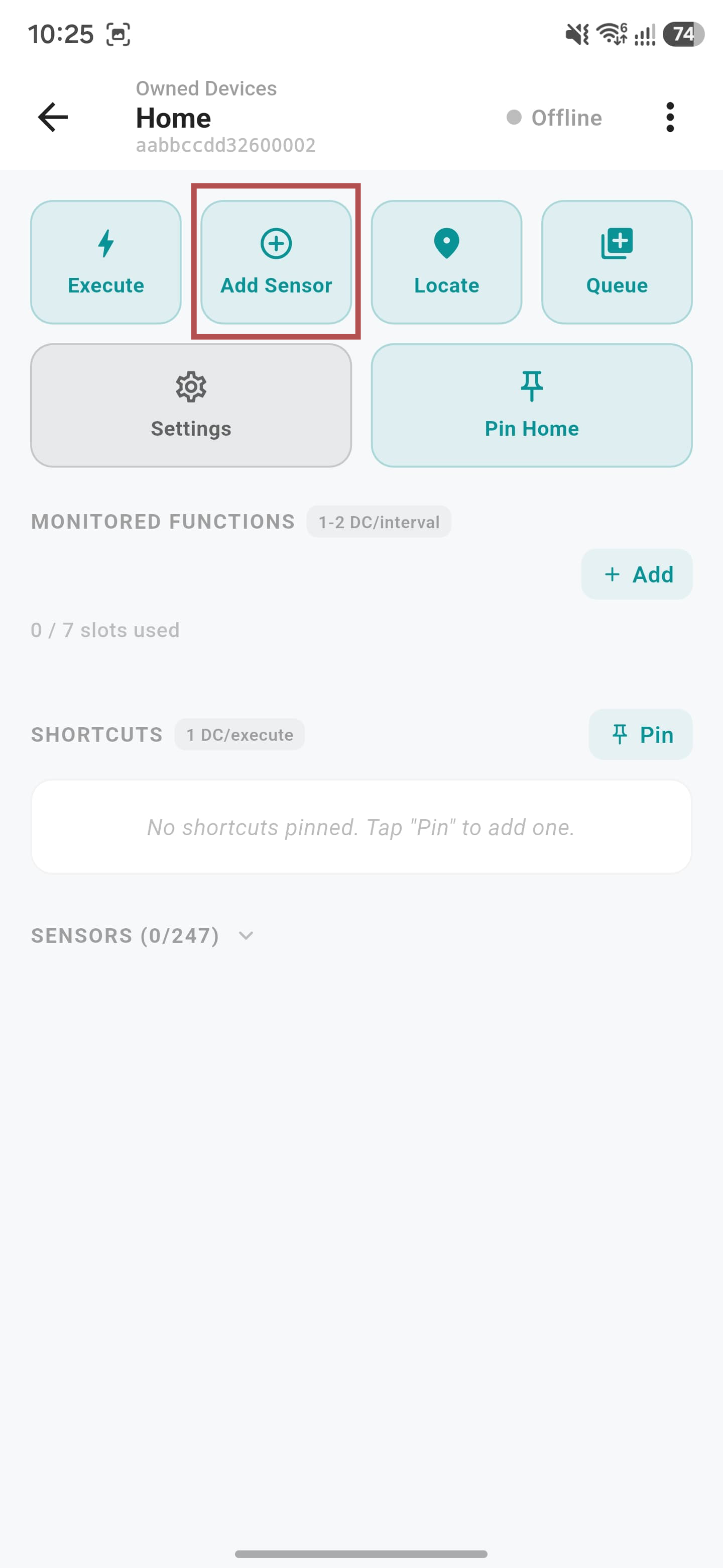
1. Tap "Add Sensor"
From the device page, start the add-sensor flow.

2. Fill in the sensor details
Name the sensor and set its Modbus address.
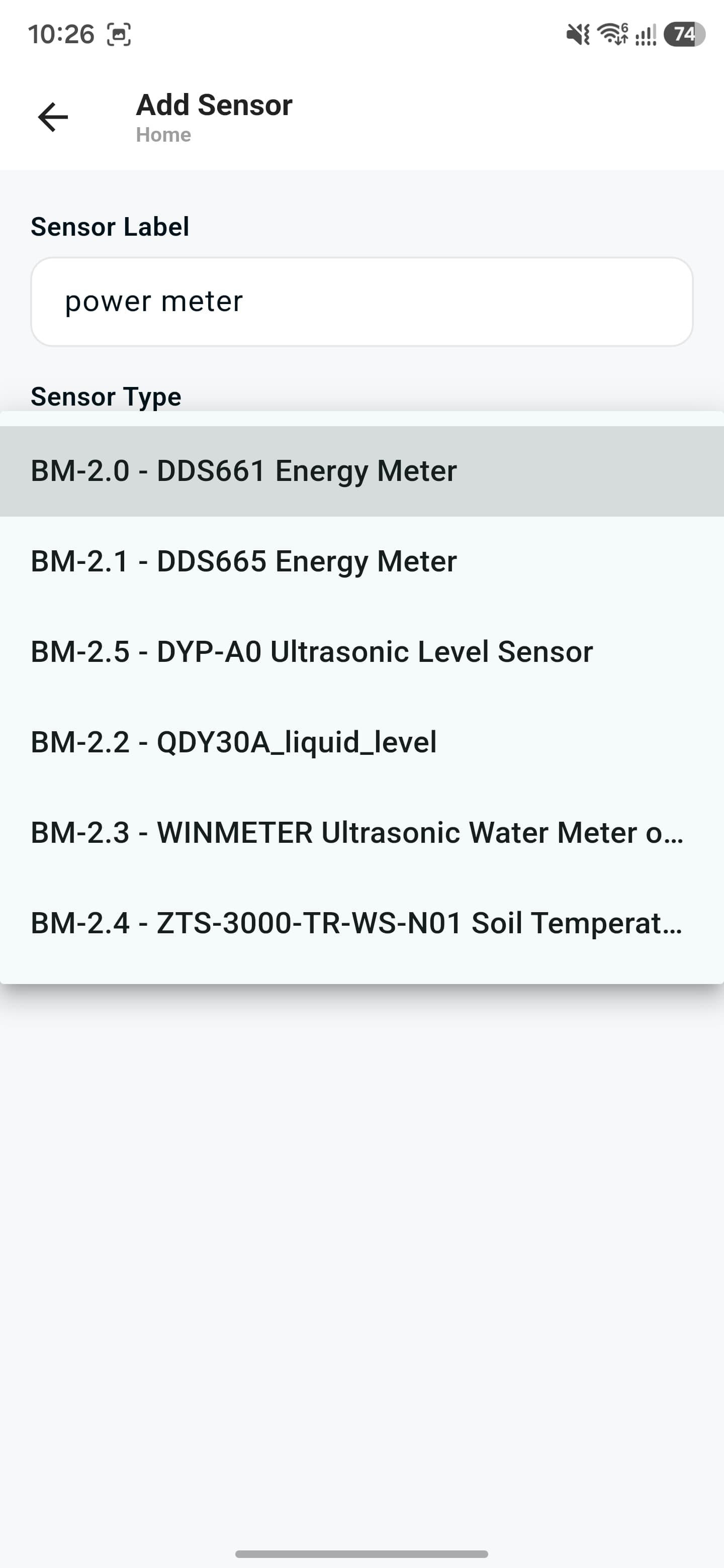
3. Choose the sensor type
Pick the matching model from the supported sensor list.
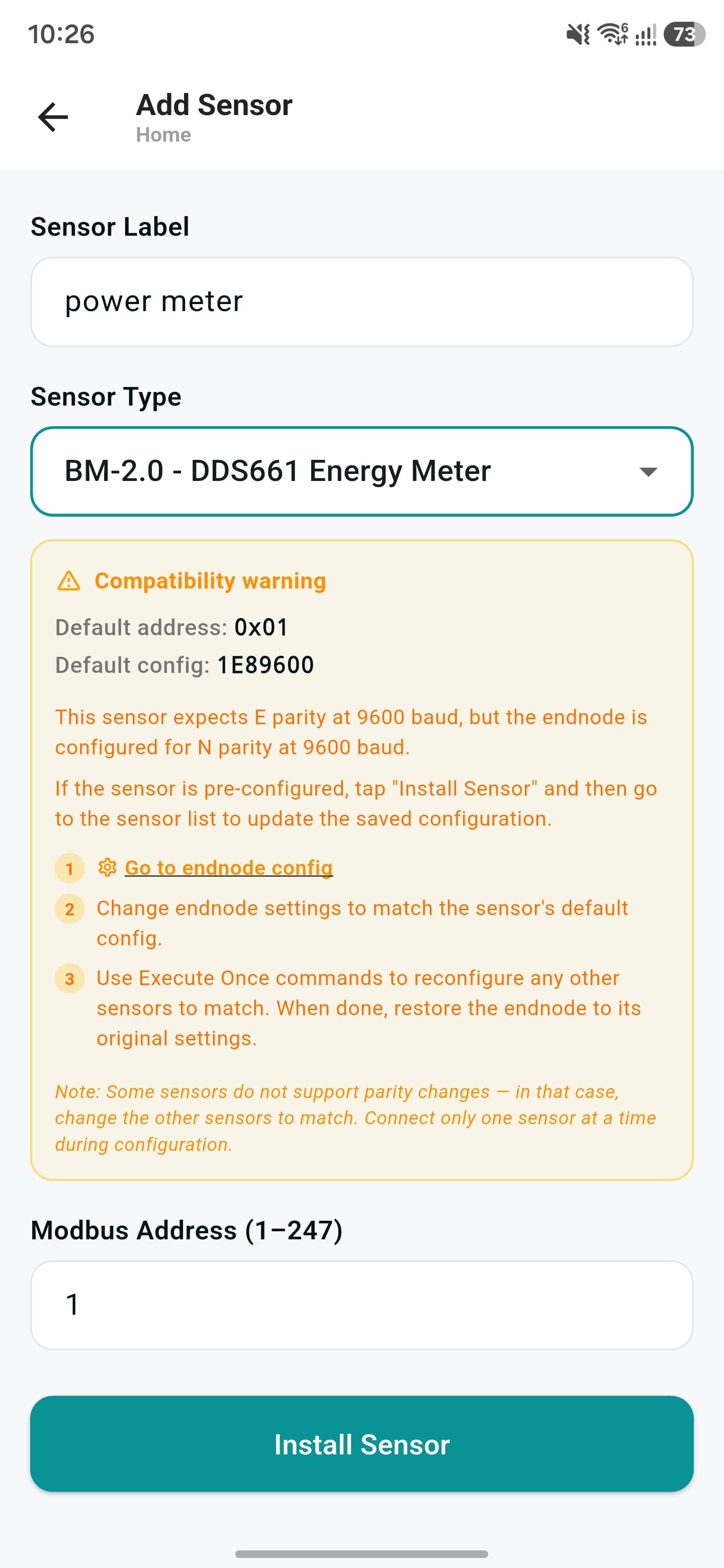
4. Resolve any compatibility warning
If the sensor's default config doesn't match the endnode, follow the steps shown to reconfigure it.
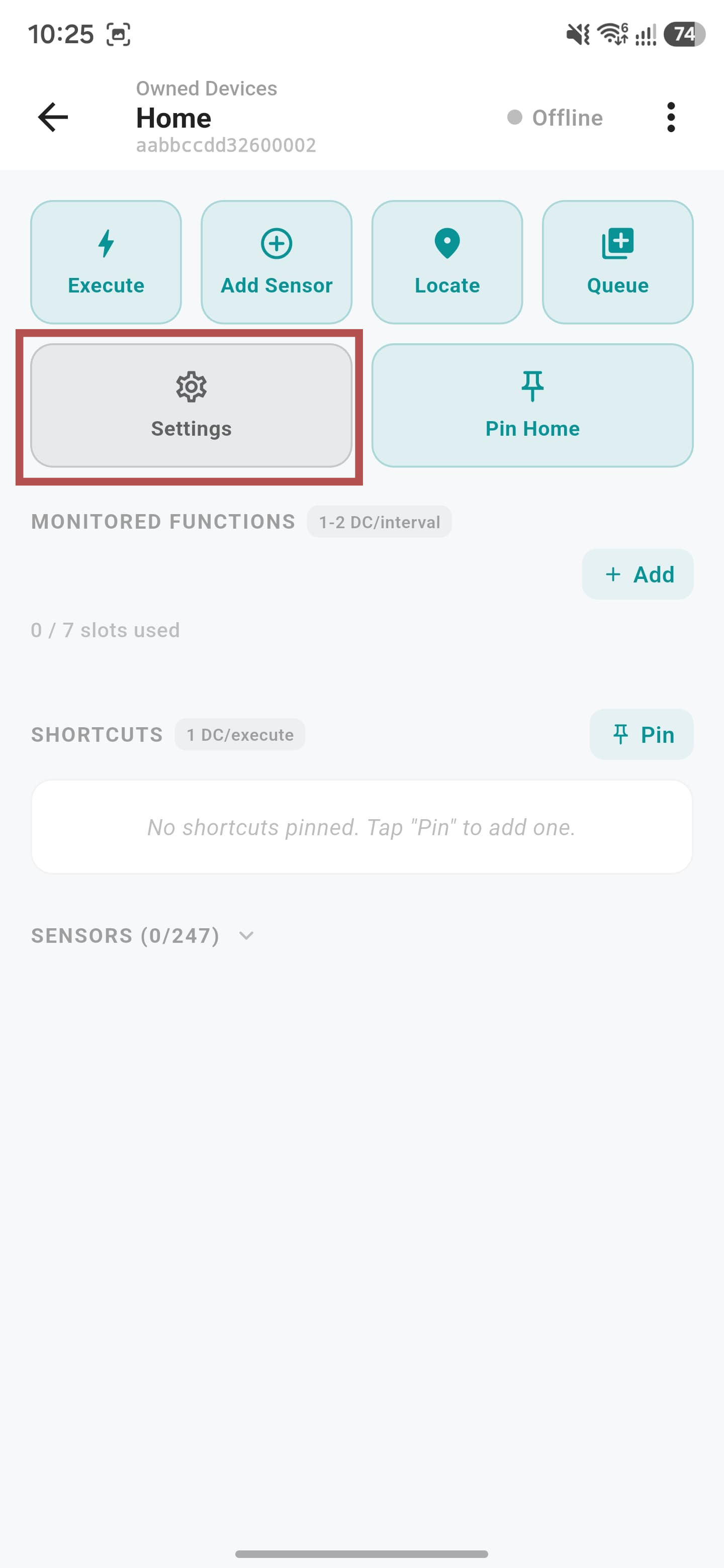
1. Open endnode configuration
From the device page, open the endnode configuration screen.
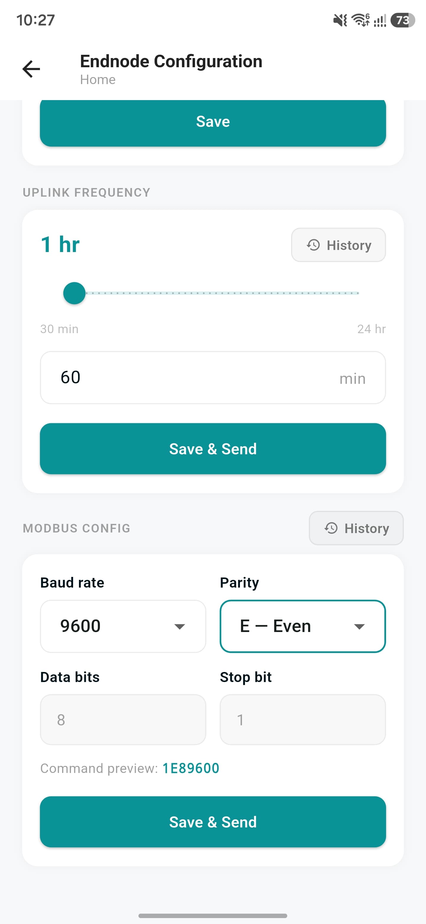
2. Change the Modbus config to match the sensor
Set the uplink frequency, then match the baud rate, parity, data bits, and stop bit to your sensor's defaults, and tap "Save & Send".
Monitored functions are functions that get saved on the device itself and sent automatically on every uplink interval. A device can have up to 7 monitored slots.
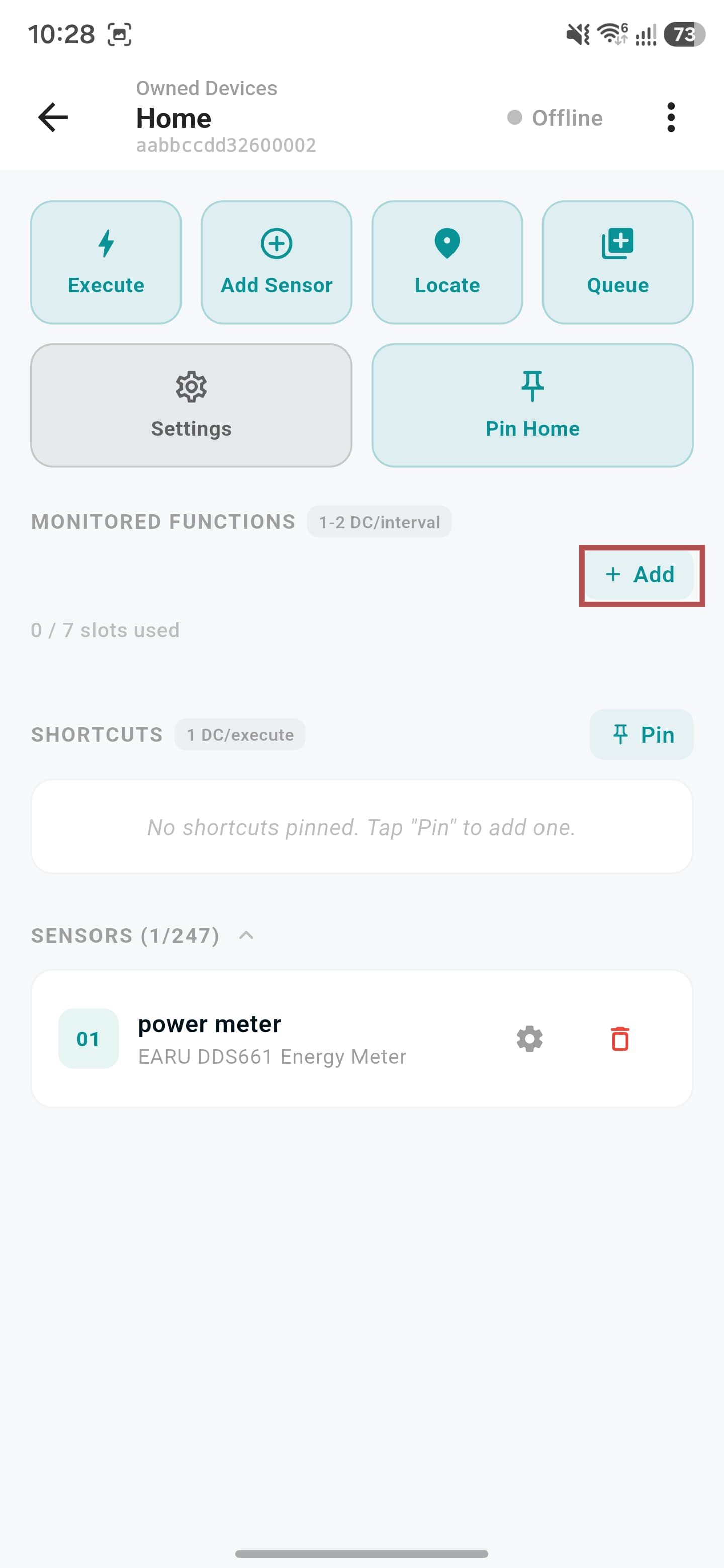
1. Tap "+ Add"
Under Monitored Functions on the device page, start adding a new slot.
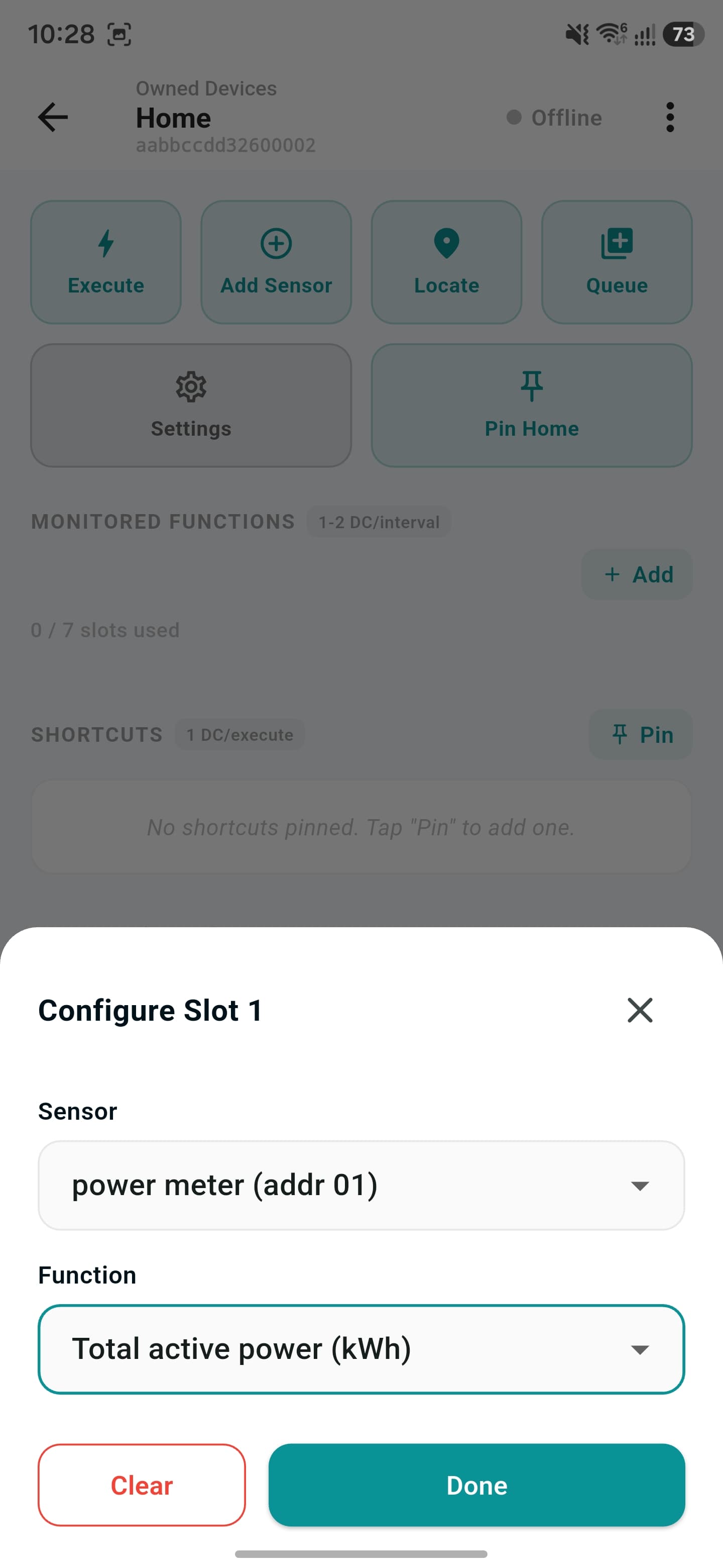
2. Choose the sensor and function
Pick which sensor and reading to monitor, then tap "Done".
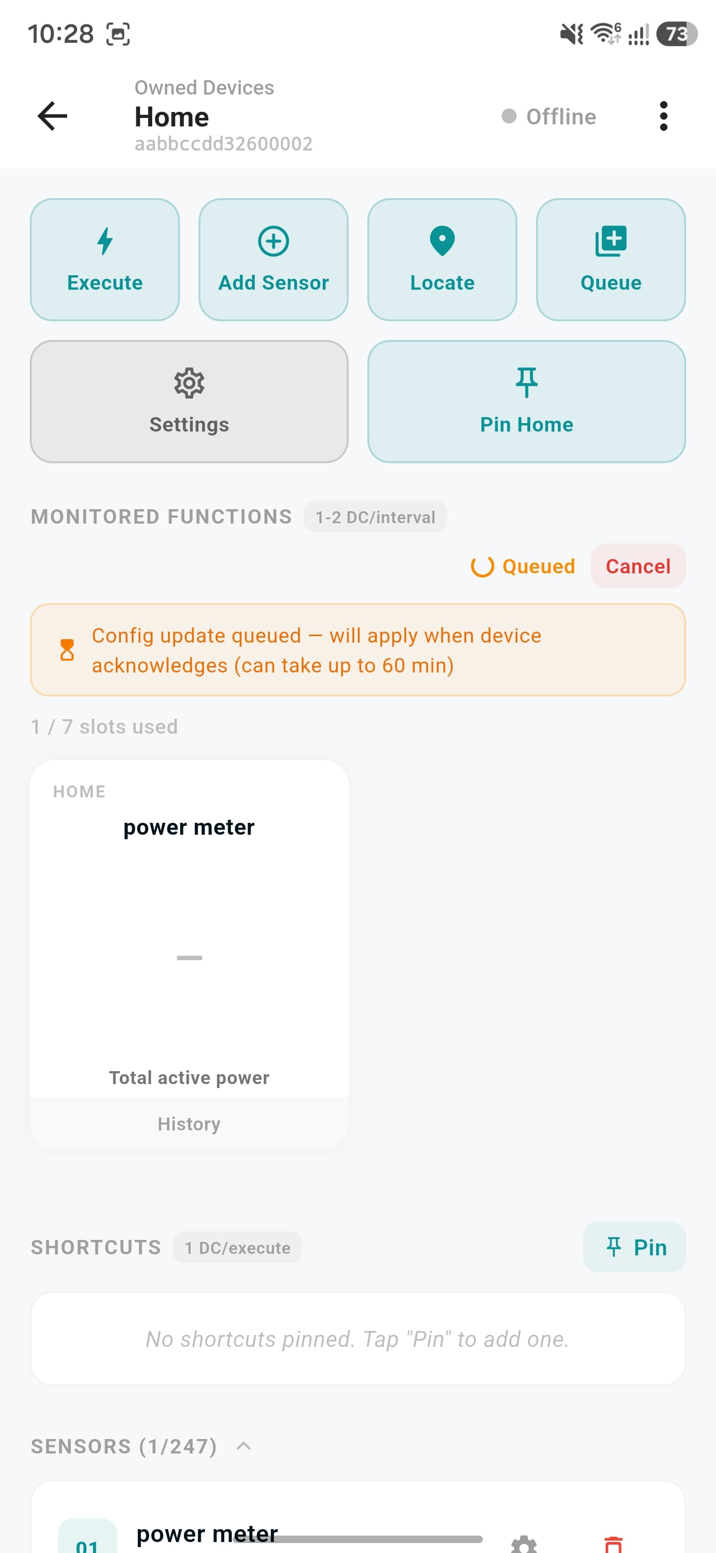
3. Config is queued
The device needs to reboot to receive the new configuration — it's applied once the device reconnects and acknowledges it (can take up to 60 min).
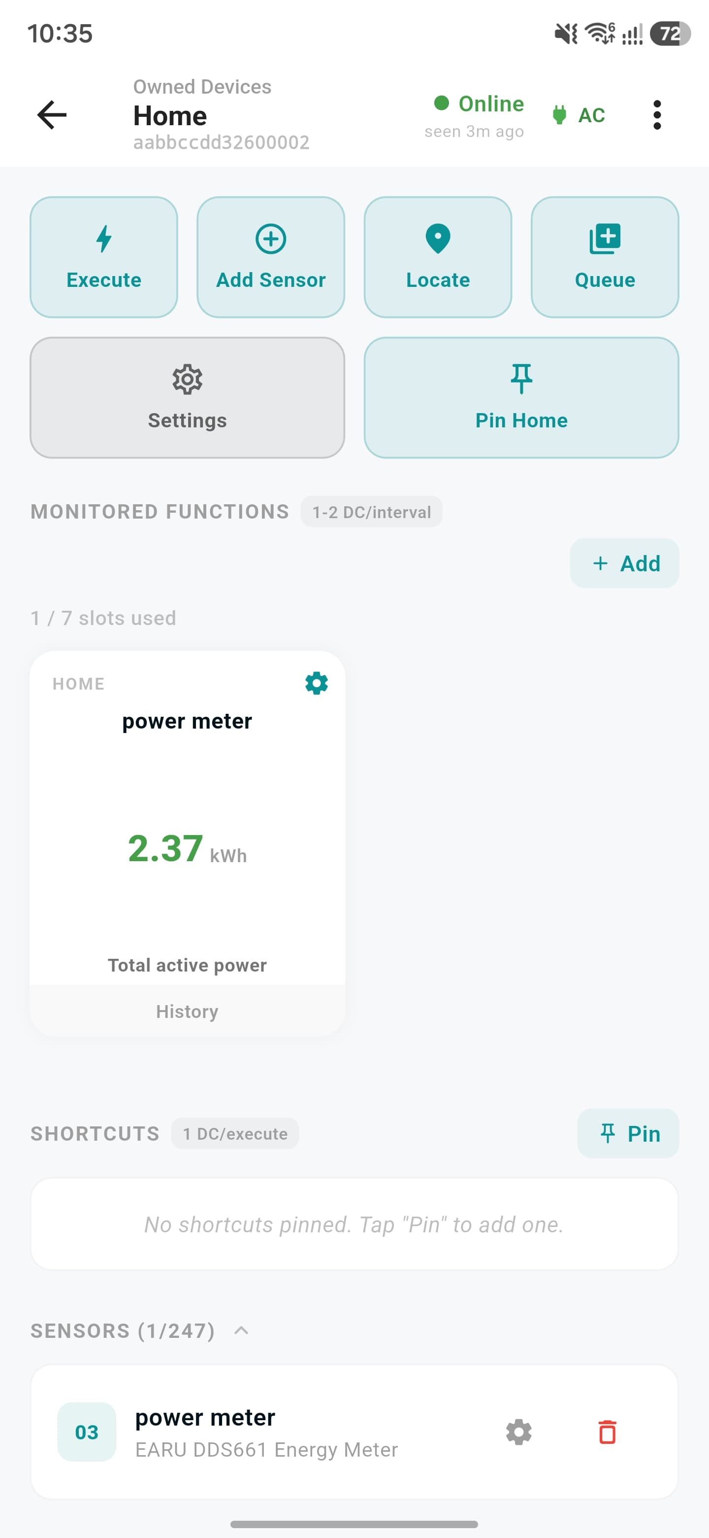
4. Readings start coming in
Once the device reboots and reconnects, the monitored slot starts showing live readings.
It's possible to execute commands once — like changing a sensor's Modbus address or activating a relay — without saving them as a monitored slot.
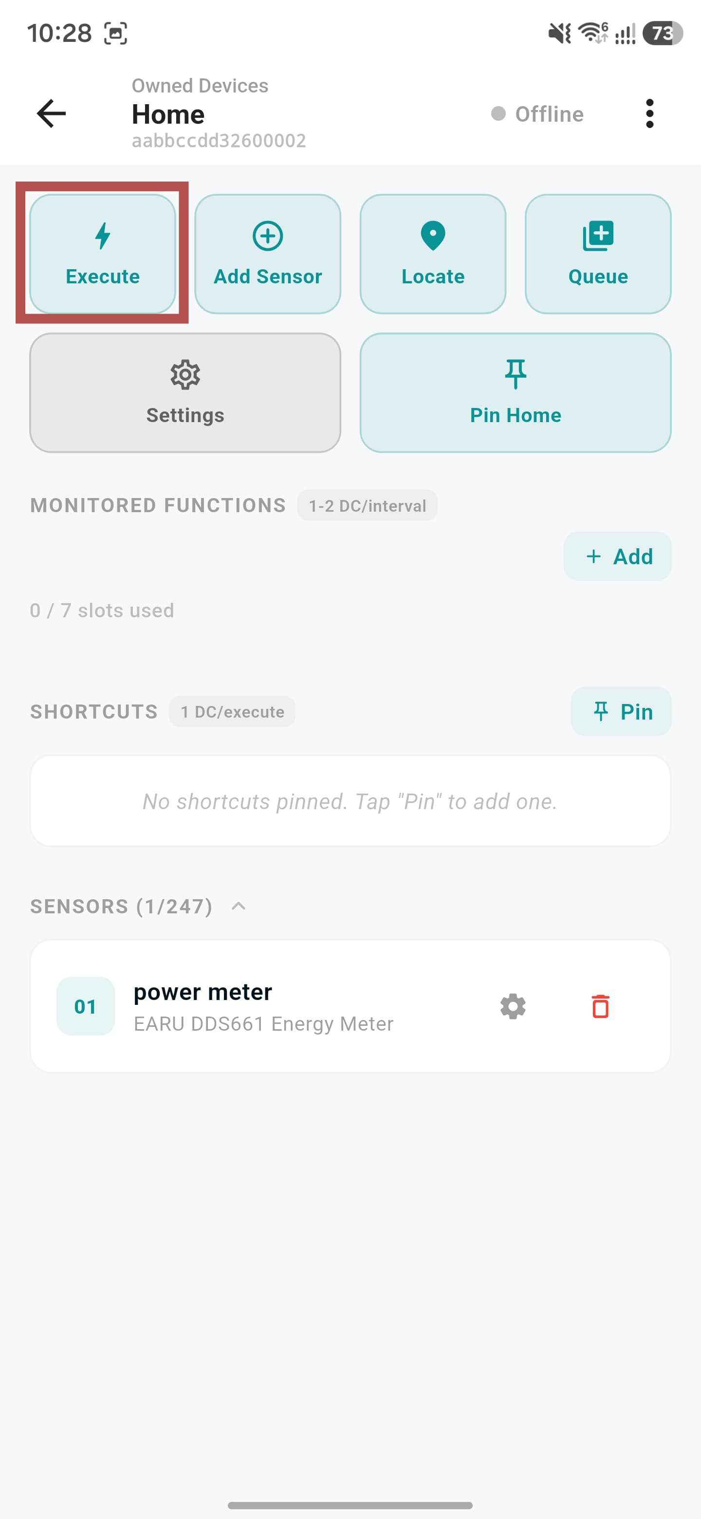
1. Tap "Execute"
From the device page, start the execute-once flow.
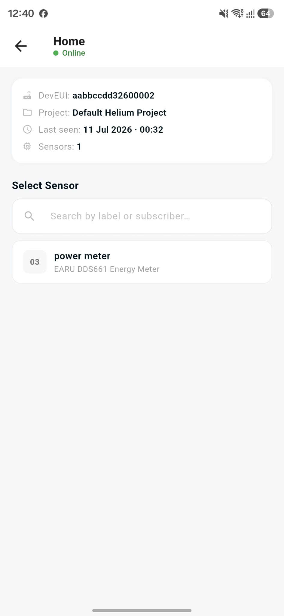
2. Select the sensor
Choose which sensor the command should be sent to.
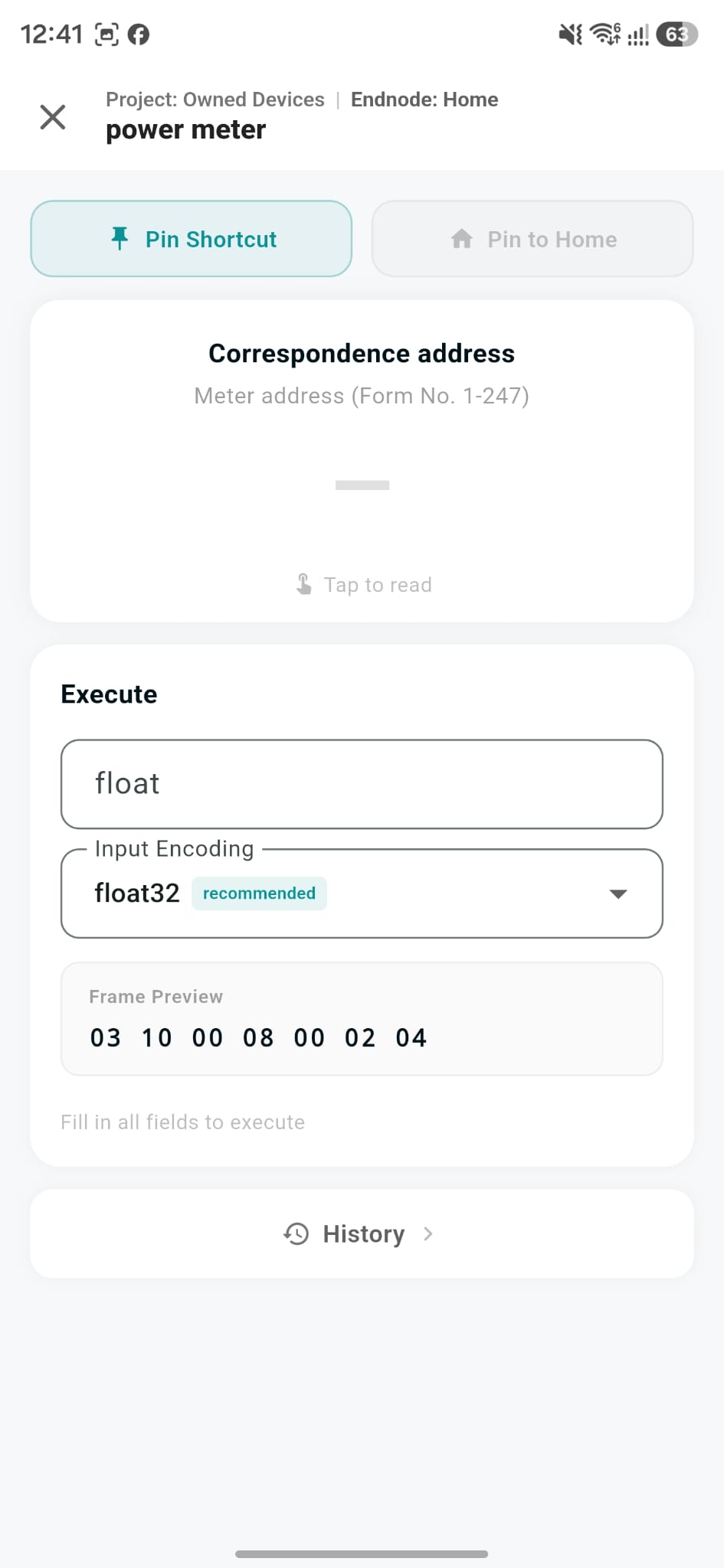
3. Fill in and execute
Set the value and encoding, preview the frame, then execute — optionally pin it as a shortcut for next time.
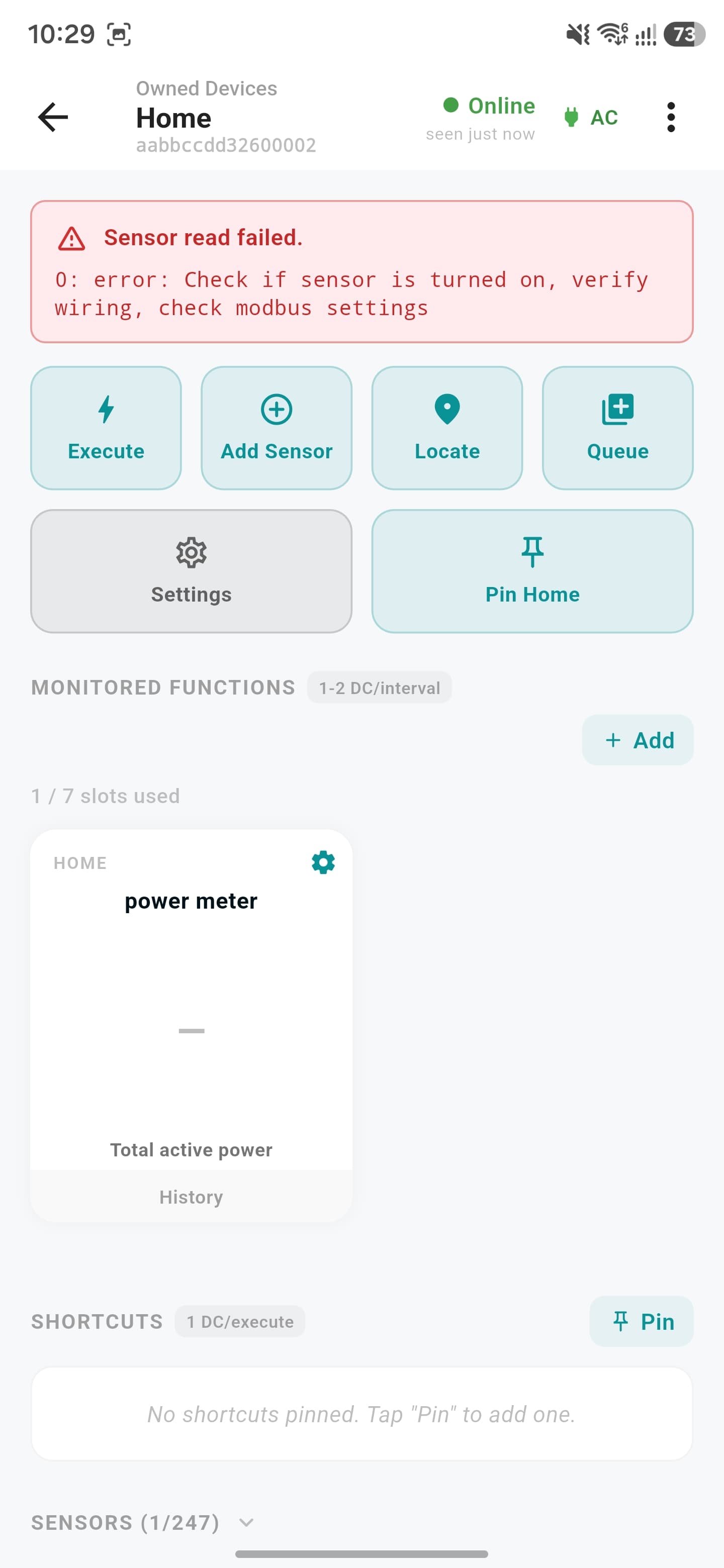
Errors come with a hint
If a sensor read fails, a red banner explains what to check.
Business Admin Account
Full control over your projects, devices, and billing from the web dashboard.
Check your email
You'll get an email with a password for your new account.
Change your password
Set a new password to secure your account.
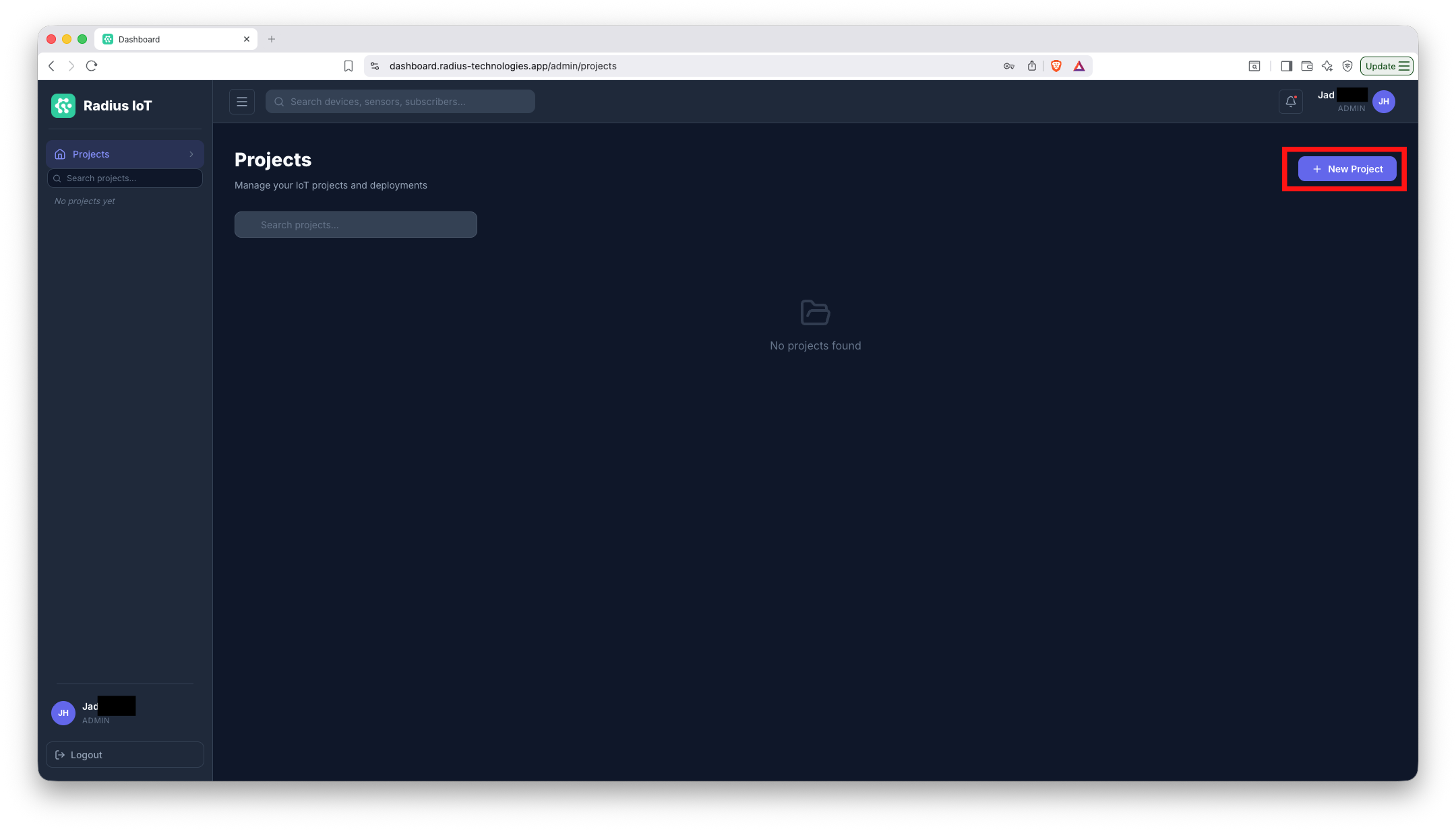
1. Start from the Projects page
Your Projects page starts empty — tap "New Project" to create your first one.
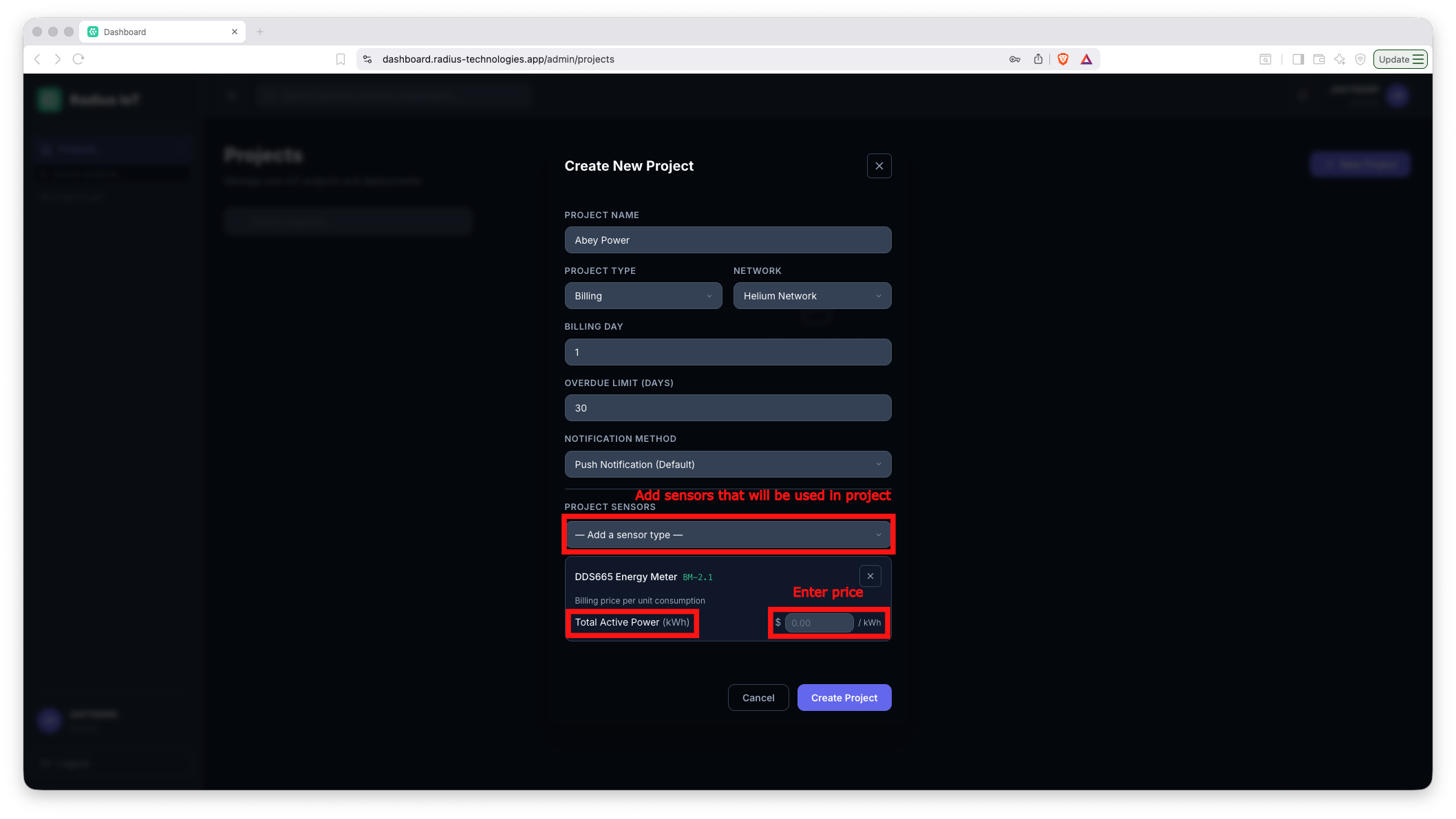
2. Create the project
Fill in the project details and confirm.
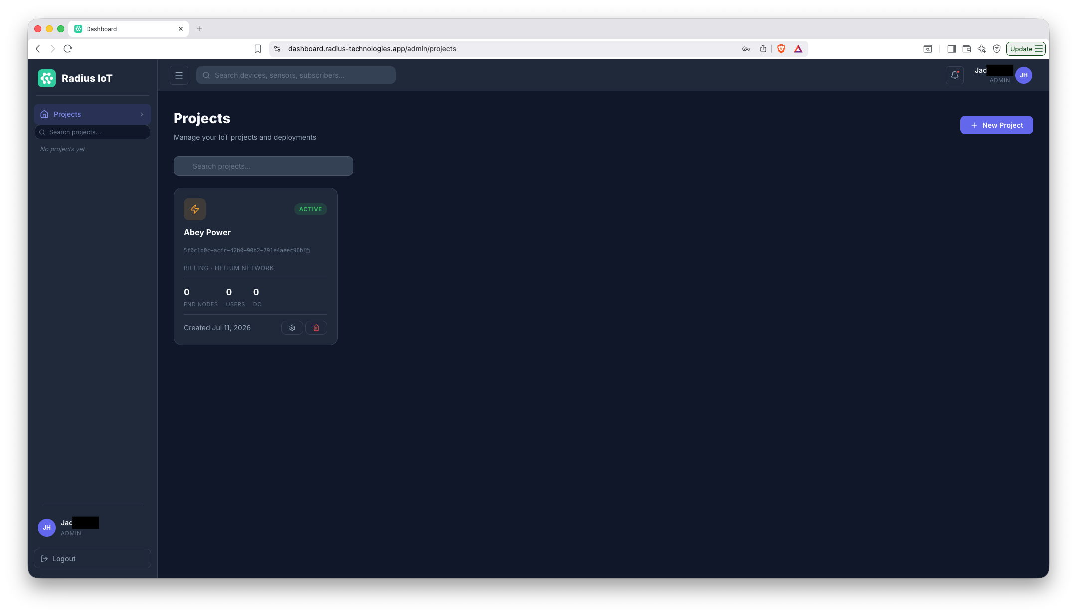
3. It's added to your list
The new project now shows up on your Projects page.
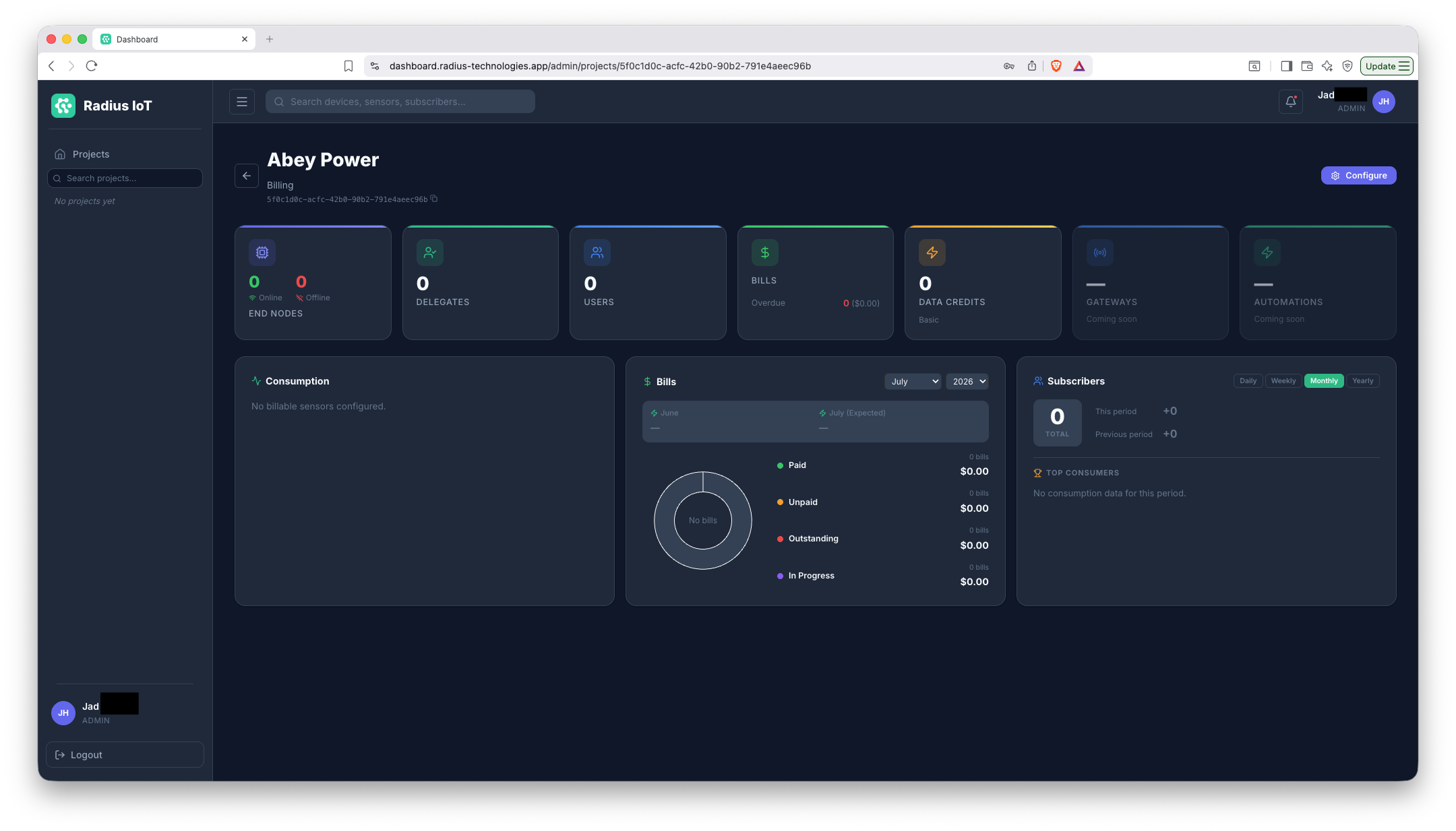
4. Open the project
Click into it to manage devices, sensors, delegates, and billing.
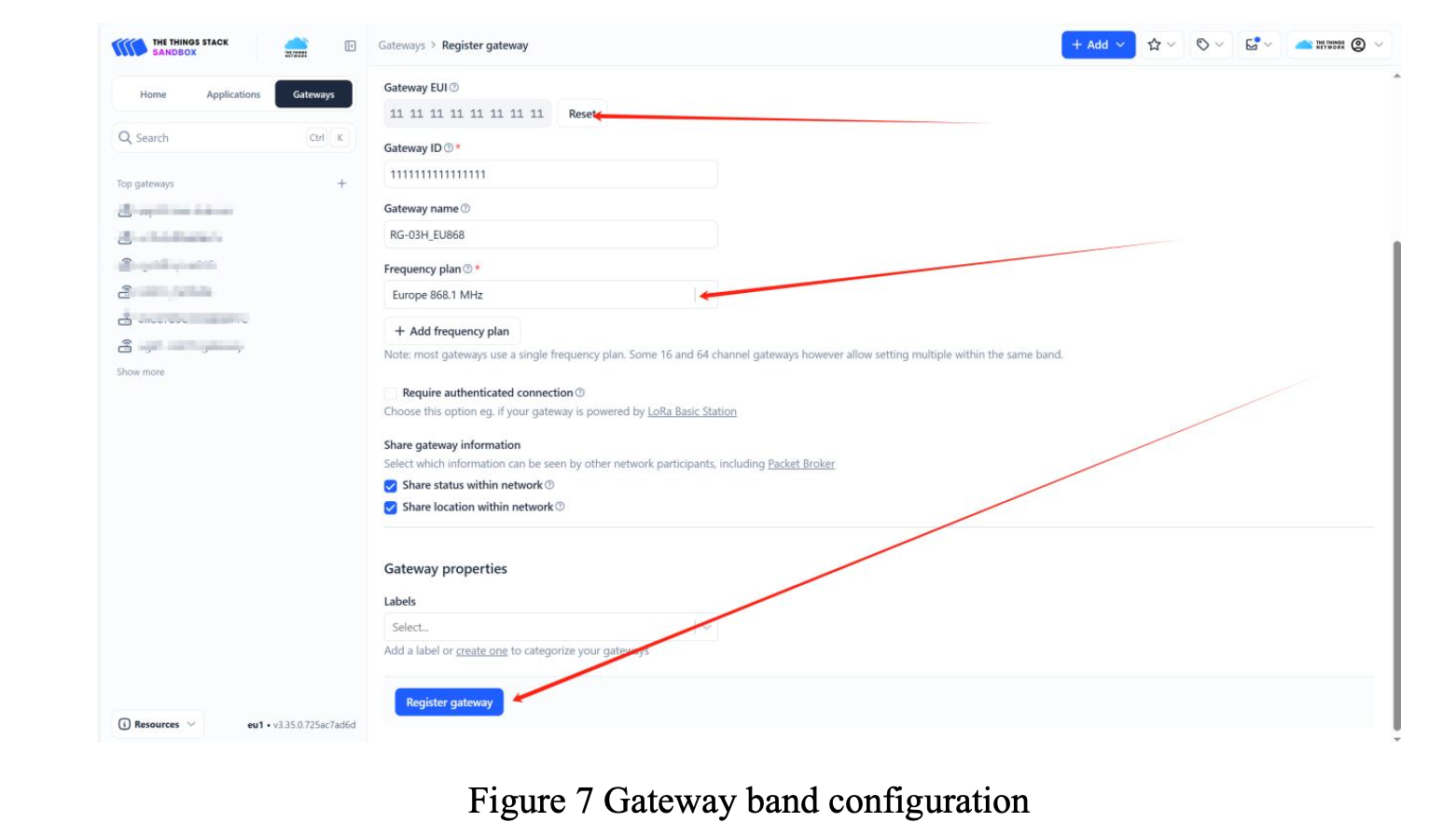
1. Set up your gateway on TTN
Register your gateway on The Things Network (TTN). Consult the datasheet of your gateway model for its frequency plan and other setup details.
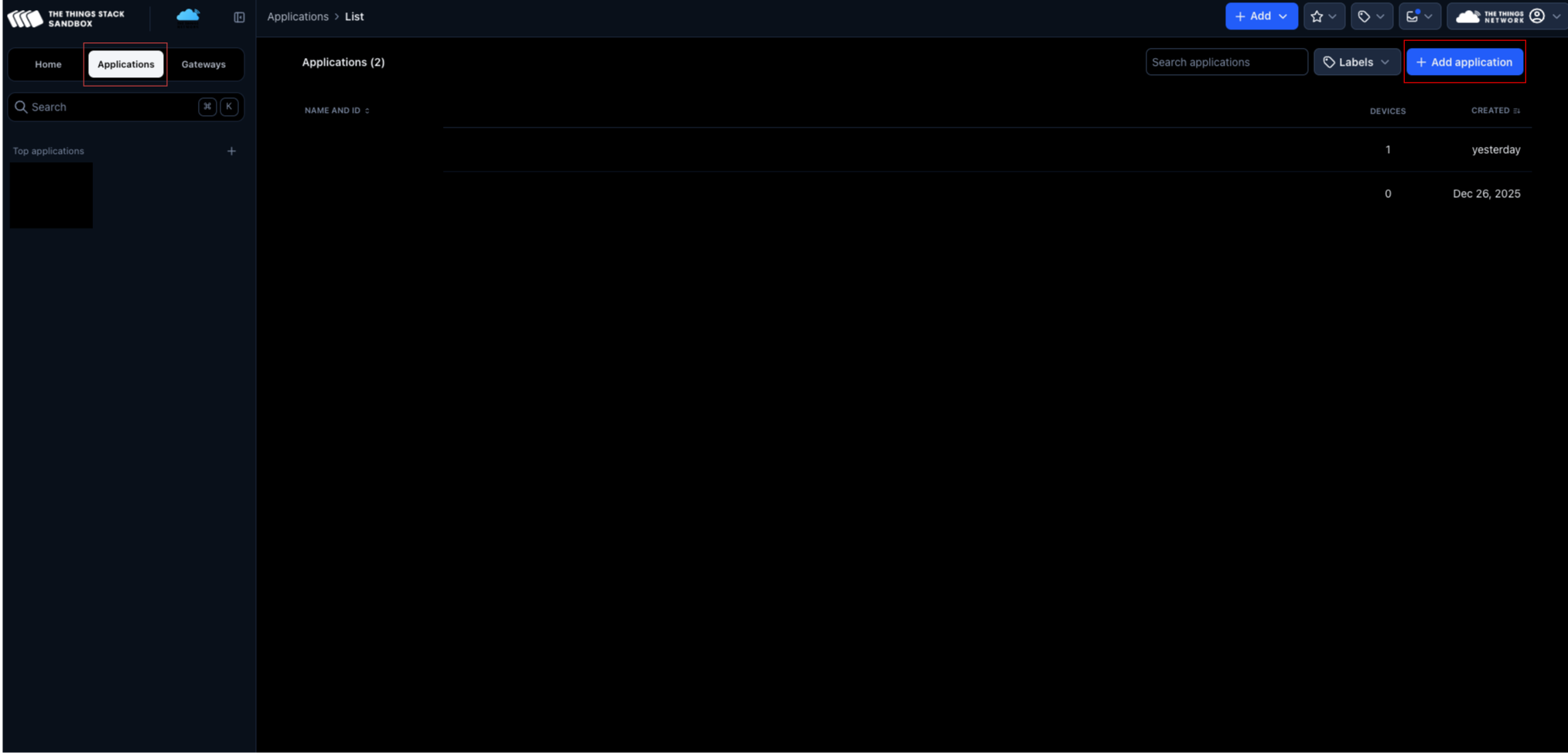
2. Create an application
Create a new application on TTN for your gateway's devices.
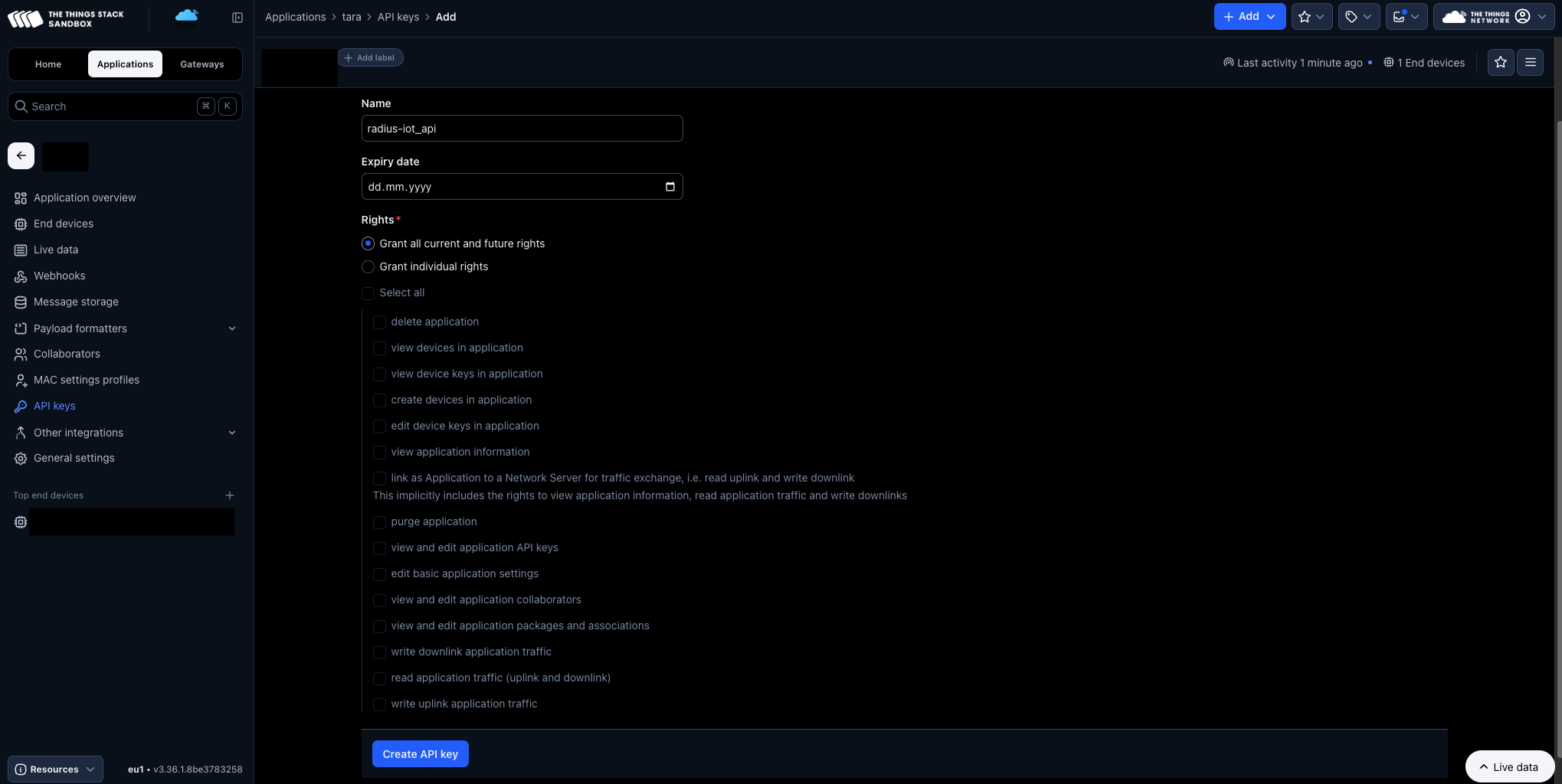
3. Create an API key
In the application's API keys page, create a new key with full rights.
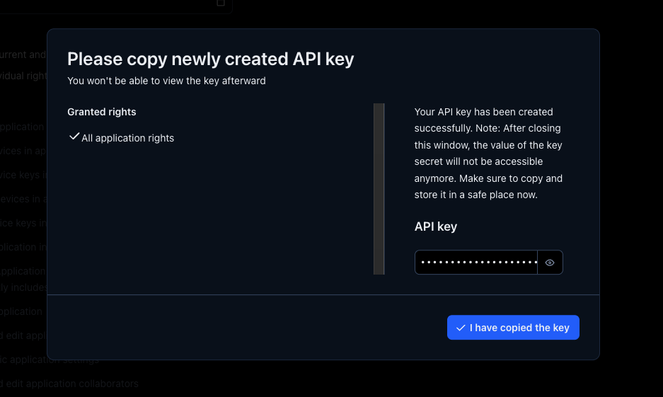
4. Copy the API key
Copy it now — you won't be able to view it again after closing this window.
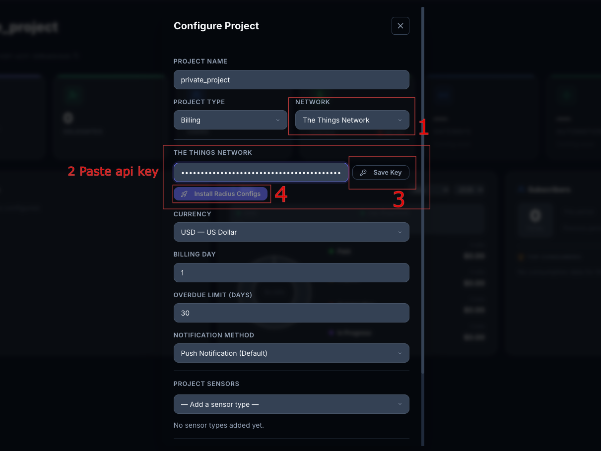
5. Connect it in the Radius IoT dashboard
Log in with your admin account and create a new project. Select "The Things Network", paste the API key, click "Save Key", then click "Install Radius Configs".
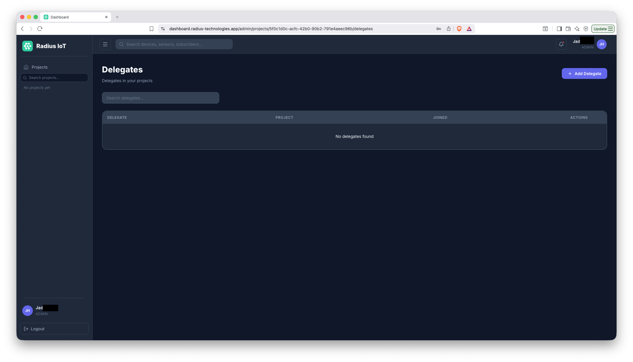
1. Add delegate email
Open the project and invite a delegate by entering their email address.
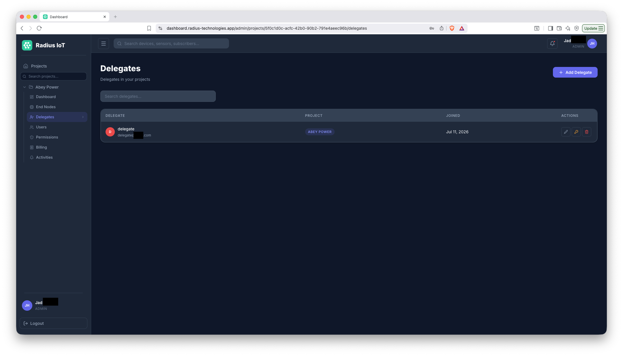
2. Delegate added
They now appear on the project with management access — the delegate should log into the app using that same email.
These steps are performed by a delegate from the mobile app, after they've logged in.
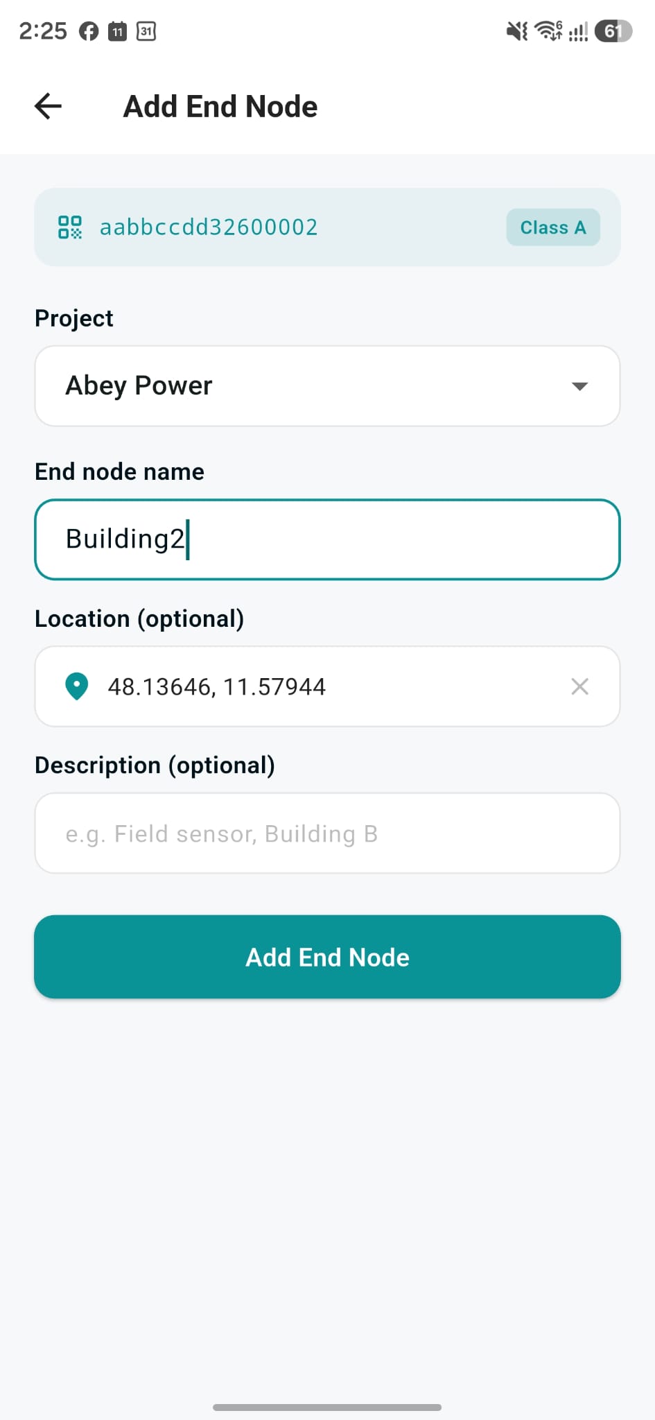
1. Scan the end node
Scan the end node and select the respective project.
2. Add a sensor
Tap "Add Sensor" from the device page to attach a sensor.
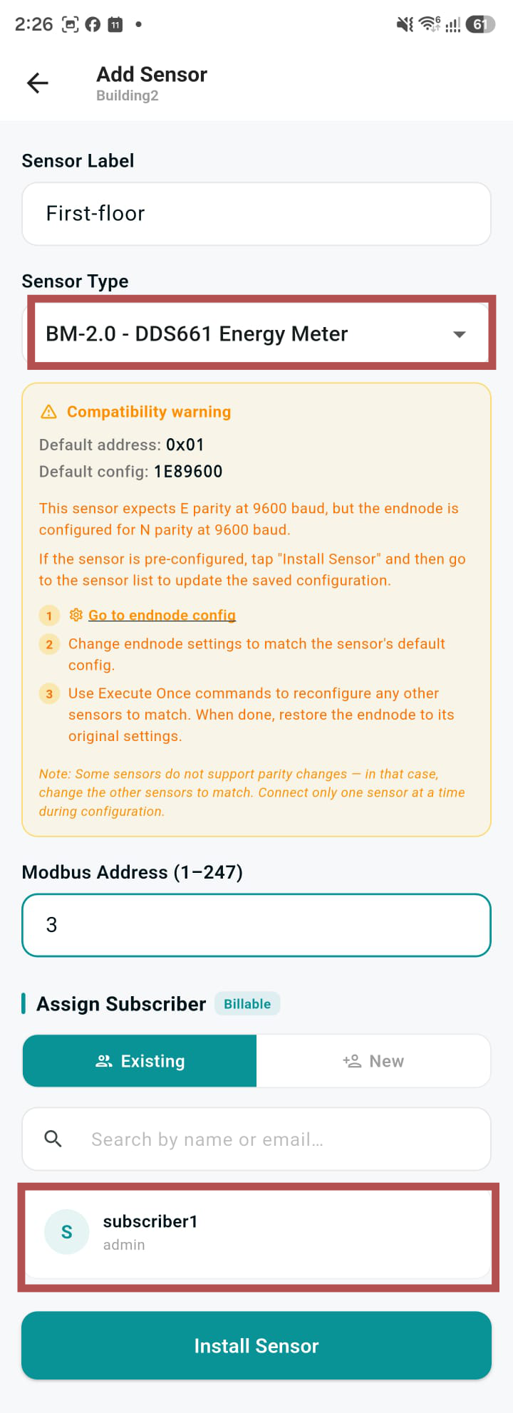
3. Assign it to a subscriber
Select the sensor type from the project's sensors and assign the sensor to a subscriber.
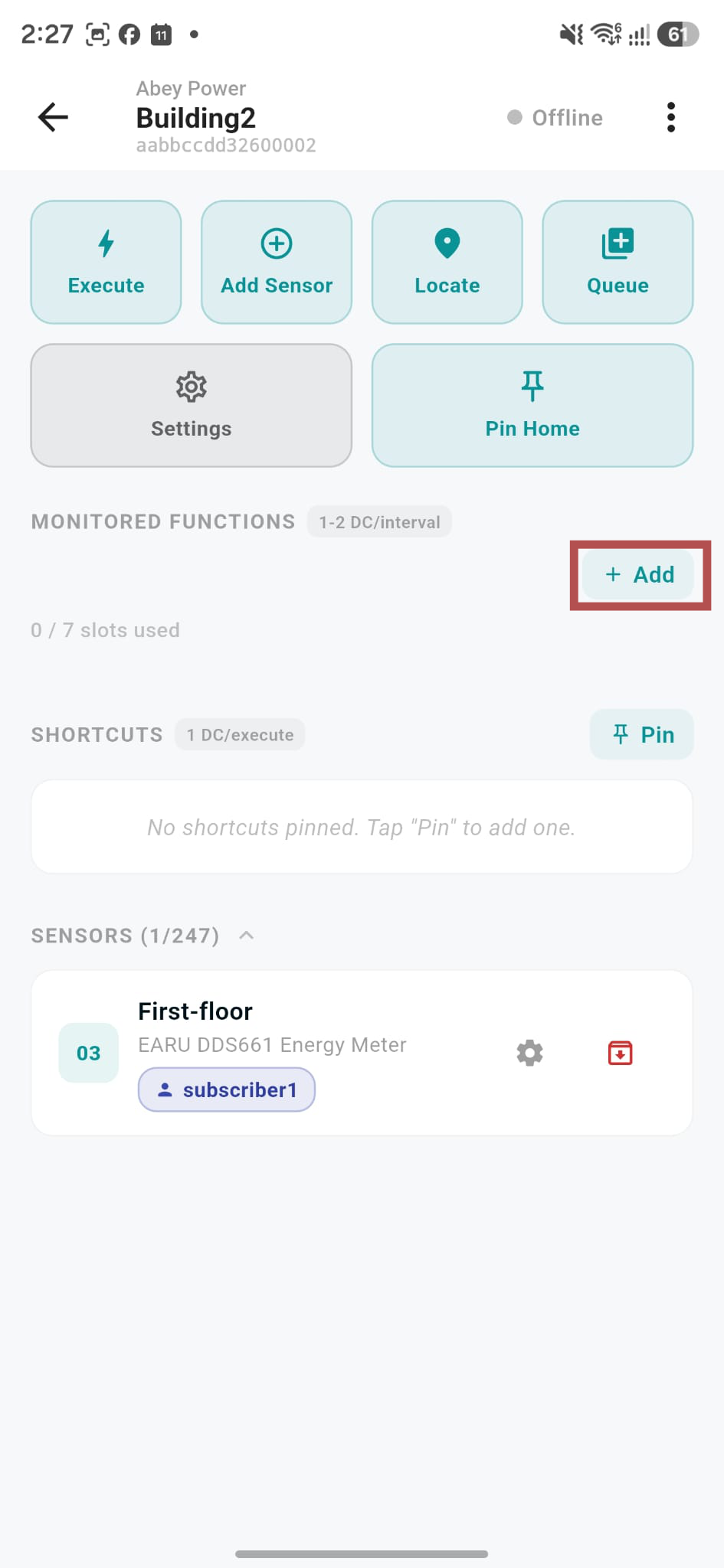
4. Add a monitored function
Add a monitored function for the sensor.
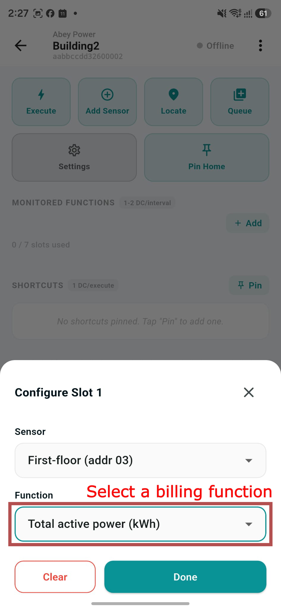
5. Select the billing function
Choose which of the monitored functions the subscriber will be billed on.
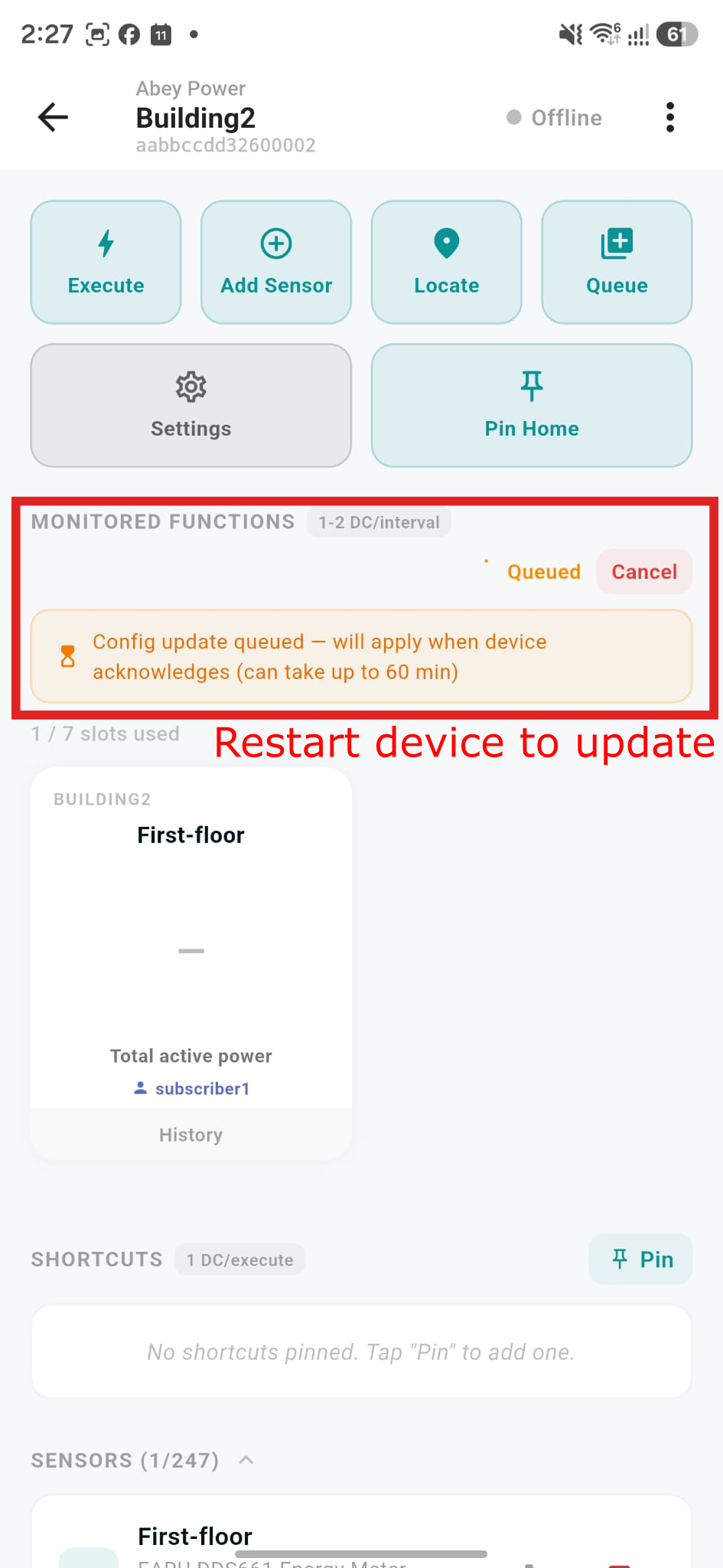
6. Update the Radius device
Restart the device, or wait for its next message, to apply the update.
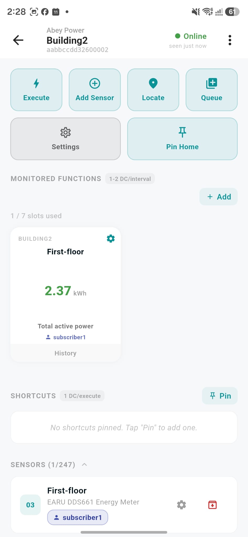
7. All set
You should see the function reading with the name of the subscriber attached.
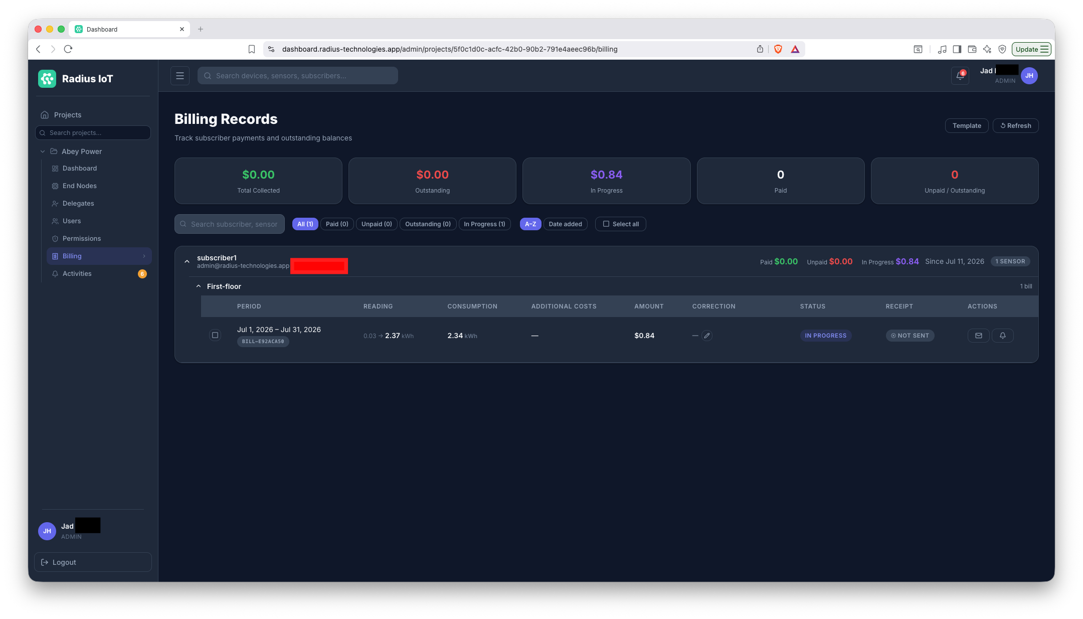
1. Manage billing
Manage billing rates and statements from the dashboard.
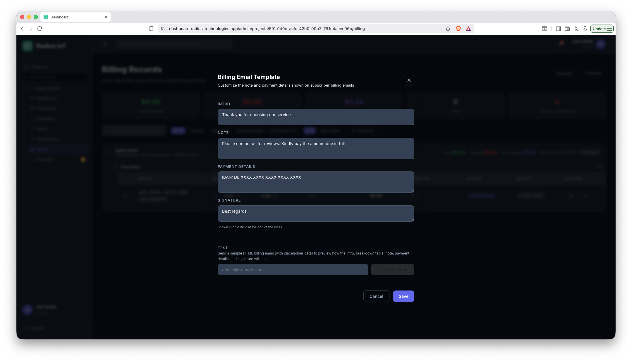
2. Customize the billing email
Edit the email template sent to subscribers with their billing statement.
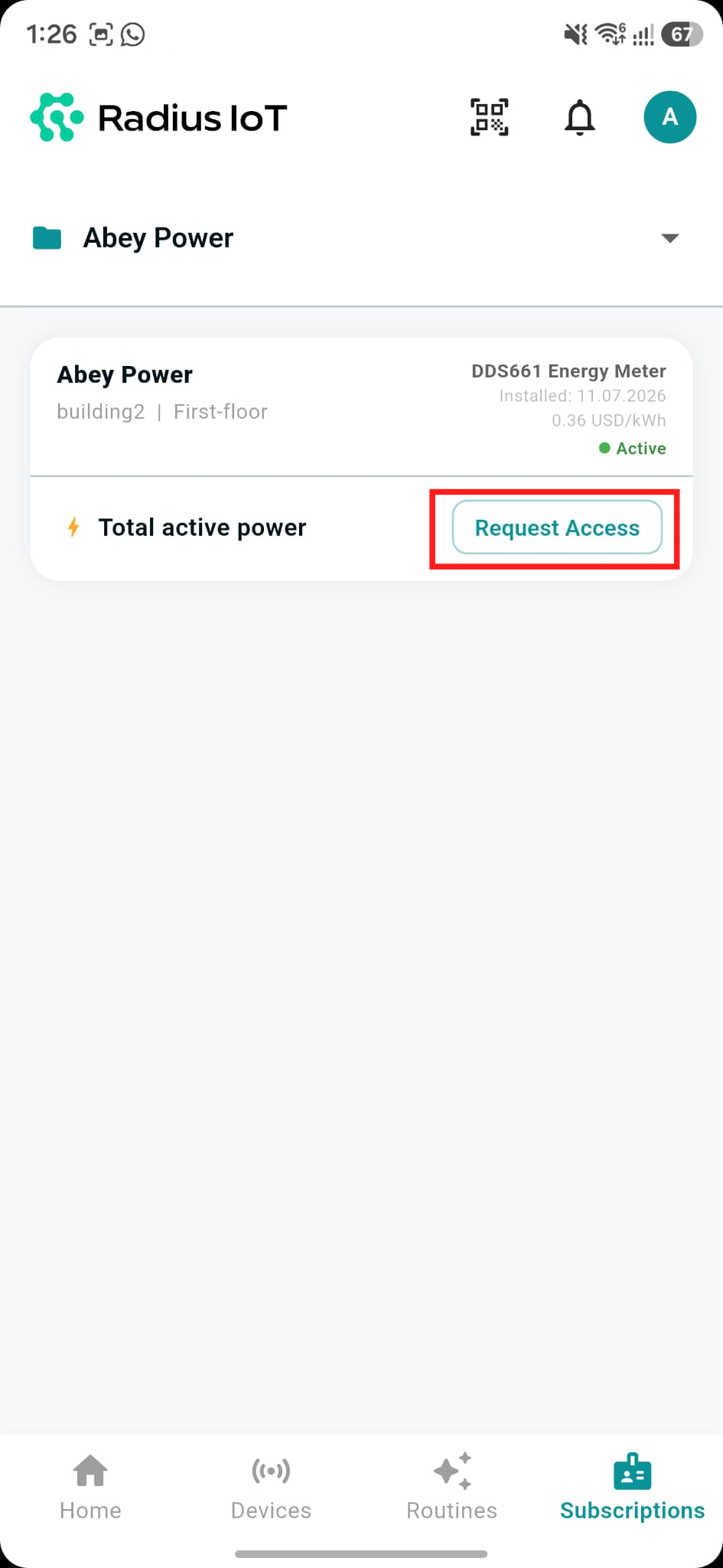
1. Request access
Subscribers request access to a billed sensor from the app.
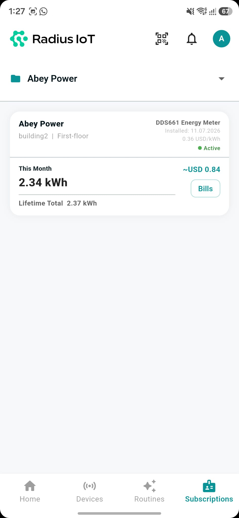
2. Access granted
Once approved, they see their usage and estimated cost.
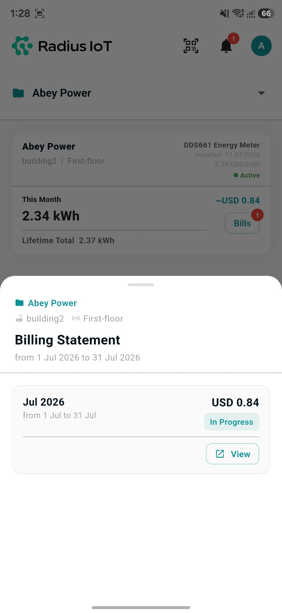
3. View billing history
Subscribers can view past and in-progress billing statements.
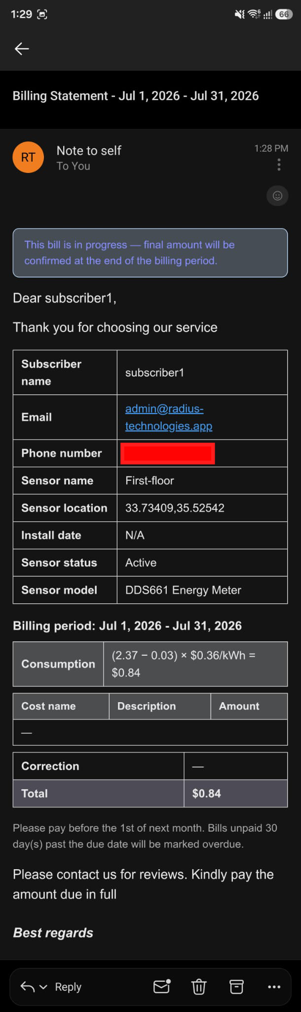
4. Billing statement email
A detailed billing statement is emailed for each period.